精品文档---下载后可任意编辑外文文献及中文翻译学生姓名:学号:学 院:系 名:电子与计算机科学技术系专 业:电子科学与技术指导老师:2024 年 6 月RS-422 and RS-485 application noteChapter 1: OverviewIntroduction The purpose of this application note is to describe the main elements of an RS-422 and RS-485 system. This application note attempts to cover enough technical details so that the system designer will have considered all the important aspects in his data system design. Since both RS-422 and RS-485 are data transmission systems that use balanced differential signals, it is appropriate to discuss both systems in the same application note. Throughout this application note the generic terms of RS-422 and RS-485 will be used to represent the EIA/TIA-422 and EIA/TIA-485 Standards.
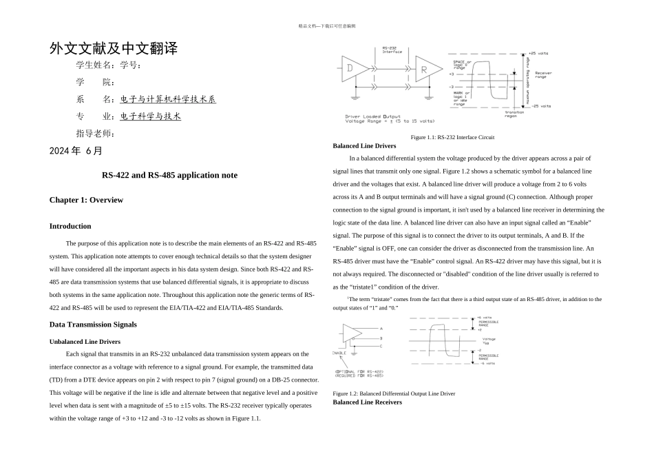
Data Transmission Signals Unbalanced Line DriversEach signal that transmits in an RS-232 unbalanced data transmission system appears on the interface connector as a voltage with reference to a signal ground. For example, the transmitted data (TD) from a DTE device appears on pin 2 with respect to pin 7 (signal ground) on a DB-25 connector. This voltage will be negative if the line is idle and alternate between that negative level and a positive level when data is sent with a magnitude of ±5 to ±15 volts. The RS-232 receiver typically operates within the voltage range of +3 to +12 and -3 to -12 volts as shown in Figure 1.1.Figure 1.1: RS-232 Interface CircuitBalanced Line DriversIn a balanced differential system the voltage produced by the driver appears across a pair of signal lines that transmit only one signal. Figure 1.2 shows a schematic symbol for a balanced line driver and the voltages that exist. A balanced line driver will pr...