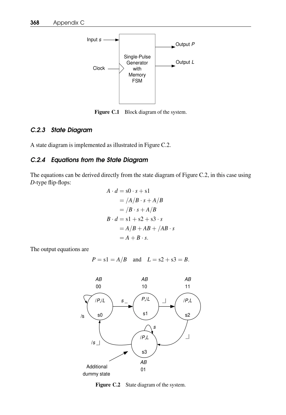
Appendix C: Tutorial on theUse of Verilog HDL to Simulatea Finite-State Machine DesignC.1INTRODUCTIONThis appendix quickly describes an FSM model in Verilog code and then simulates it usingSynaptiCAD’s VeriLogger Extreme simulator. The code for the model, VeriLogger Extreme,and the code for most of the examples in the book are contained on the CDROM provided withthe book.A more detailed account of the Verilog HDL is provided in Chapters 6–8, where the languageis developed at a slower and more defined pace.C.2THE SINGLE PULSE WITH MEMORY SYNCHRONOUS FINITE-STATEMACHINE DESIGN: USING VERILOG HDL TO SIMULATEThe design of a single-pulse generator with memory is outlined and then a Verilog HDL file iscreated. This Verilog file will use the most basic of the Verilog methods so as to keep it simple.C.2.1SpecificationWhenever input s is asserted high, a single pulse is to be generated at the output P. Signal s mustbe returned low and then reasserted high again before another pulse can be generated. Inaddition, a memory output L is to go high to indicate that a pulse has been generated; goinglow again when the s input is returned to logic 0.C.2.2Block DiagramFigure C.1 illustrates the block diagram of the system.FSM-based Digital Design using Verilog HDL Peter Minns and Ian Elliott# 2008 John Wiley & Sons, Ltd. ISBN: 978-0-470-06070-4C.2.3State DiagramA state diagram is implemented as illustrated in Figure C.2.C.2.4Equations from the State DiagramThe equations can be derived directly from the state diagram of Figure C.2, in this case usingD-type flip-flops:A � d ¼ s0 � s þ s1¼ =A=B � s þ A=B¼ =B � s þ A=BB � d ¼ s1 þ s2 þ s3 � s¼ A=B þ AB þ =AB � s¼ A þ B � s:The output ...


