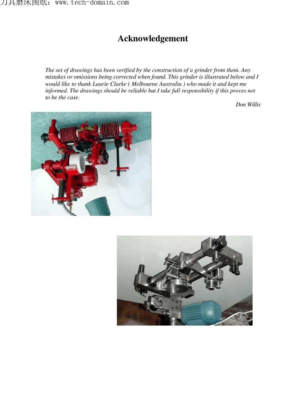
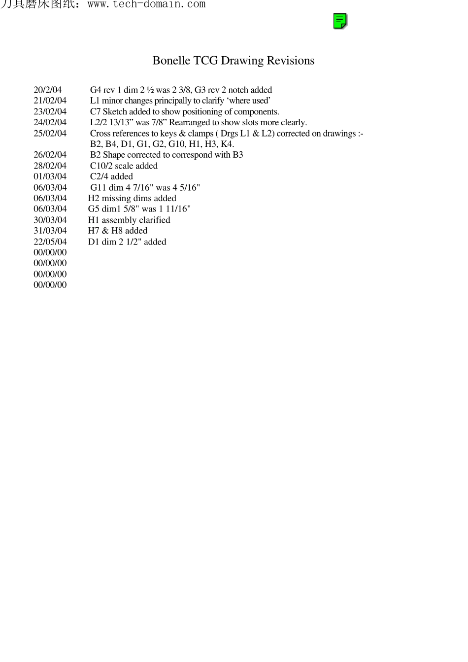
Acknow ledgement The set of drawings has been verified by the construction of a grinder from them. Any mistakes or omissions being corrected when found. This grinder is illustrated below and I would like to thank Laurie Clarke ( Melbourne Australia ) who made it and kept me informed. The drawings should be reliable but I take full responsibility if this proves not to be the case. Don Willis 刀具磨床图纸:www.tech-domain.comBonelle TCG Drawing Revisions 20/2/04 G4 rev 1 dim 2 ½ was 2 3/8, G3 rev 2 notch added 21/02/04 L1 minor changes principally to clarify ‘where used’ 23/02/04 C7 Sketch added to show positioning of components. 24/02/04 L2/2 13/13” was 7/8” Rearranged to show slots more clearly. 25/02/04 Cross references to keys & clamps ( Drgs L1 & L2) corrected on drawings :- B2, B4, D1, G1, G2, G10, H1, H3, K4. 26/02/04 B2 Shape corrected to correspond with B3 28/02/04 C10/2 scale added 01/03/04 C2/4 added 06/03/04 G11 dim 4 7/16" was 4 5/16" 06/03/04 H2 missing dims added 06/03/04 G5 dim1 5/8" was 1 11/16" 30/03/04 H1 assembly clarified31/03/04 H7 & H8 added 22/05/04 D1 dim 2 1/2" added 00/00/00 00/00/00 00/00/00 00/00/00 刀具磨床图纸:www.tech-domain.comBo n elle TCG© J.B.D.Willis DrawingsA. General Arrangement B. BaseC. Wheel headD. Wheel GuardE. Dust ContainmentF. Spindle G.Workhead H.ToolholderJ. Front BarK.Tooth RestL.Miscellaneous Conventions used.The drawings are arranged so that detail drawings followimmediately after the assembly on which they are used and bear thesame drawing prefix letter A,B, etc. Details are usually easilyidentifiable on the assembly by their appearance. Specific referenceby detail number is only made when this is not the case...