Universal Serial Bus 3.1 Specification, Revision 1.0 5-4 5.3 Connector Mating Interfaces This section defines the connector mating interfaces, including the connector interface drawings, pin assignments, and descriptions. 5.3.1 USB 3.1 Standard-A Connector 5.3.1.
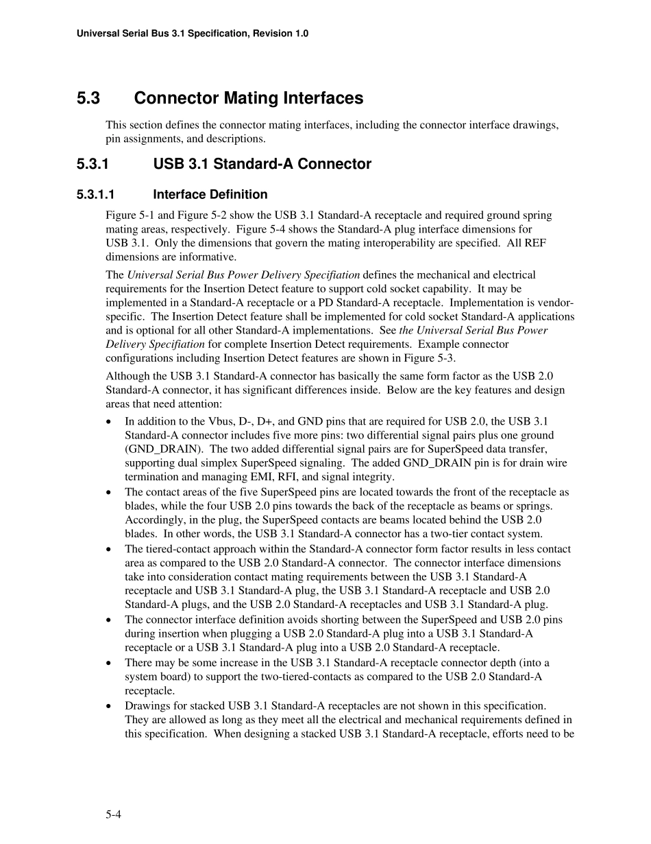
1 Interface Definition Figure 5-1 and Figure 5-2 show the USB 3.1 Standard-A receptacle and required ground spring mating areas, respectively. Figure 5-4 shows the Standard-A plug interface dimensions for USB 3.1. Only the dimensions that govern the mating interoperability are specified. All REF dimensions are informative. The Universal Serial Bus Power Delivery Specifiation defines the mechanical and electrical requirements for the Insertion Detect feature to support cold socket capability. It may be implemented in a Standard-A receptacle or a PD Standard-A receptacle. Implementation is vendor-specific. The Insertion Detect feature shall be implemented for cold socket Standard-A applications and is optional for all other Standard-A implementations. See the Universal Serial Bus Power Delivery Specifiation for complete Insertion Detect requirements. Example connector configurations including Insertion Detect features are shown in Figure 5-3. Although the USB 3.1 Standard-A connector has basically the same form factor as the USB 2.0 Standard-A connector, it has significant differences inside. Below are the key features and design areas that need attention: • In addition to the Vbus, D-, D+, and GND pins that are required for USB 2.0, the USB 3.1 Standard-A connector includes five more pins: two differential signal pairs plus one ground (GND_DRAIN). The two added differential signal pairs are for SuperSpeed data transfer, supporting dual simplex SuperSpeed signalin...