®White PaperSDR SDRAM ControllerAugust 2002, ver. 1.11M-WP-SDR-1.1IntroductionThe single data rate (SDR) synchronous dynamic random access memory (SDRAM) controller provides a simplified interface to industry standard SDR SDRAM. The SDR SDRAM Controller is available in either Verilog HDL or VHDL and is optimized for the Altera® APEX™ architecture. 
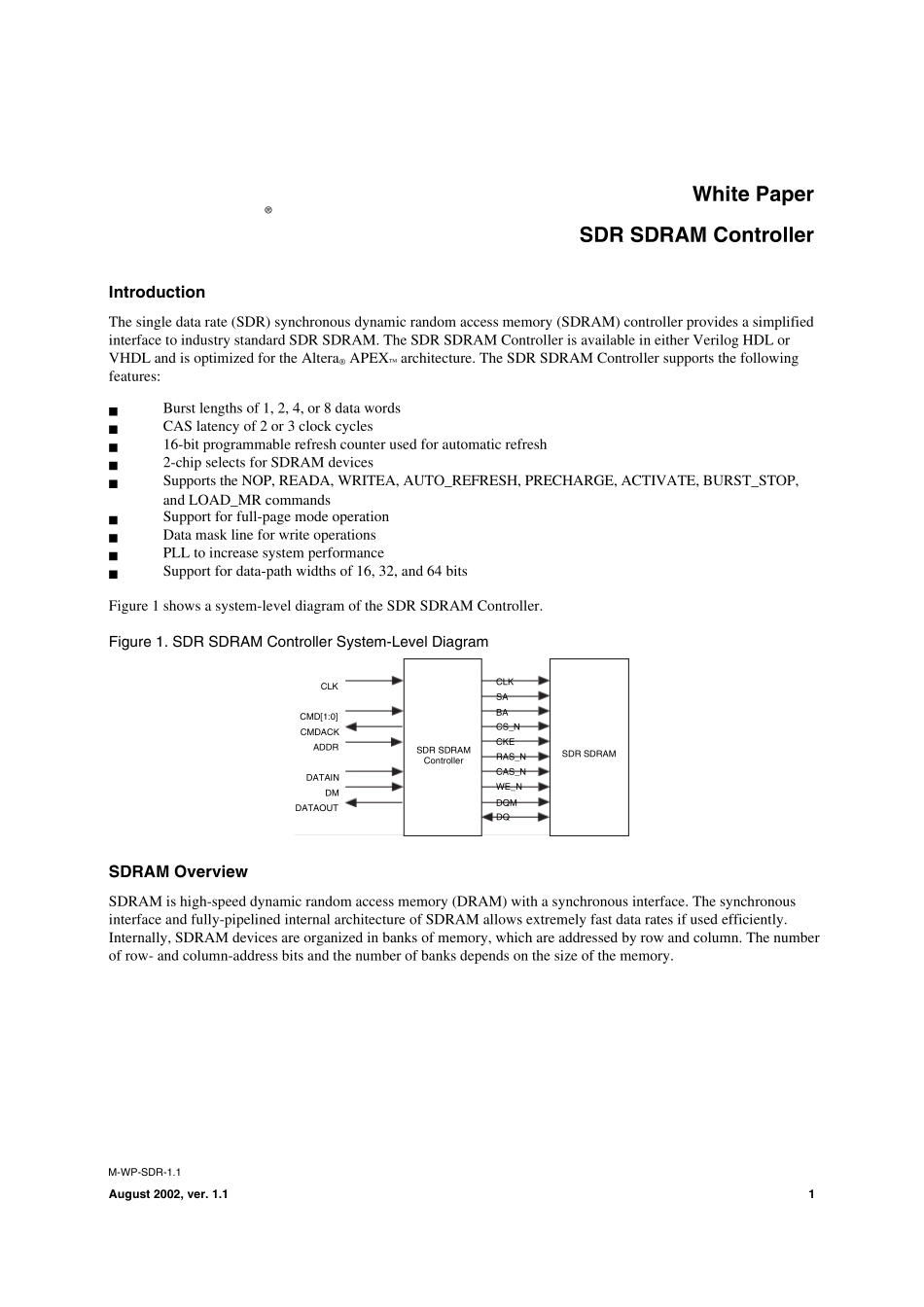
The SDR SDRAM Controller supports the following features:■Burst lengths of 1, 2, 4, or 8 data words■CAS latency of 2 or 3 clock cycles■16-bit programmable refresh counter used for automatic refresh■2-chip selects for SDRAM devices■Supports the NOP, READA, WRITEA, AUTO_REFRESH, PRECHARGE, ACTIVATE, BURST_STOP, and LOAD_MR commands■Support for full-page mode operation■Data mask line for write operations■PLL to increase system performance■Support for data-path widths of 16, 32, and 64 bitsFigure 1 shows a system-level diagram of the SDR SDRAM Controller.Figure 1. SDR SDRAM Controller System-Level DiagramSDRAM OverviewSDRAM is high-speed dynamic random access memory (DRAM) with a synchronous interface. The synchronous interface and fully-pipelined internal architecture of SDRAM allows extremely fast data rates if used efficiently. Internally, SDRAM devices are organized in banks of memory, which are addressed by row and column. The number of row- and column-address bits and the number of banks depends on the size of the memory.SDR SDRAM ControllerSDR SDRAMCLKSACS_NBACKEDQCAS_NWE_NDQMRAS_NCLKCMD[1:0]CMDACKADDRDATAINDMDATAOUTAltera CorporationSDR SDRAM Controller White Paper2SDRAM is controlled by bus commands that are formed using combinations of the RASN, CASN, and WEN signals. For instance, on a clock cycle where all three signals are high, the associated command is a no operat...