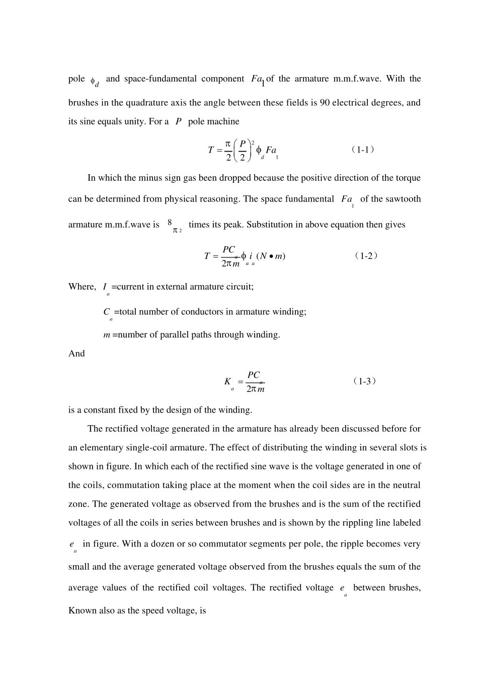
英文原文+中文翻译 (原文:)Introdu ction to D.C. Machines D.C. machines are characterized by their versatility. By means of various combinations of shunt-, series-, and separately excited field windings they can be designed to display a wide variety of volt-ampere or speed-torque characteristics for both dynamic and steady state operation. Because of the ease with which they can be controlled, systems of D.C. machines are often used in applications requiring a wide range of motor speeds or precise control of motor output. The essential features of a D.C. machine are shown schematically. The stator has salient poles and is excited by one or more field coils. The air-gap flux distribution created by the field winding is symmetrical about the centerline of the field poles. This is called the field axis or direct axis. As we know, the A.C. voltage generated in each rotating armature coil is converted to D.C. in the external armature terminals by means of a rotating commutator and stationary brushes to which the armature leads are connected. The commutator-brush combination forms a mechanical rectifier, resulting in a D.C. armature voltage as well as an armature m.m.f. Wave then is 90 electrical degrees from the axis of the field poles, i.e. in the quadrature axis. In the schematic representation the brushes are shown in quadrature axis because this is the position of the coils to which they are connected. The armature m.m.f. Wave then is along the brush axis as shown. (The geometrical position of the brushes in an actual machine is approximately 90 electrical degrees from their position in the schematic diagram because of the shape of the end connections to the commutator.) The magnetic torque a...


