Configu re the S7-200 PLC 1. 
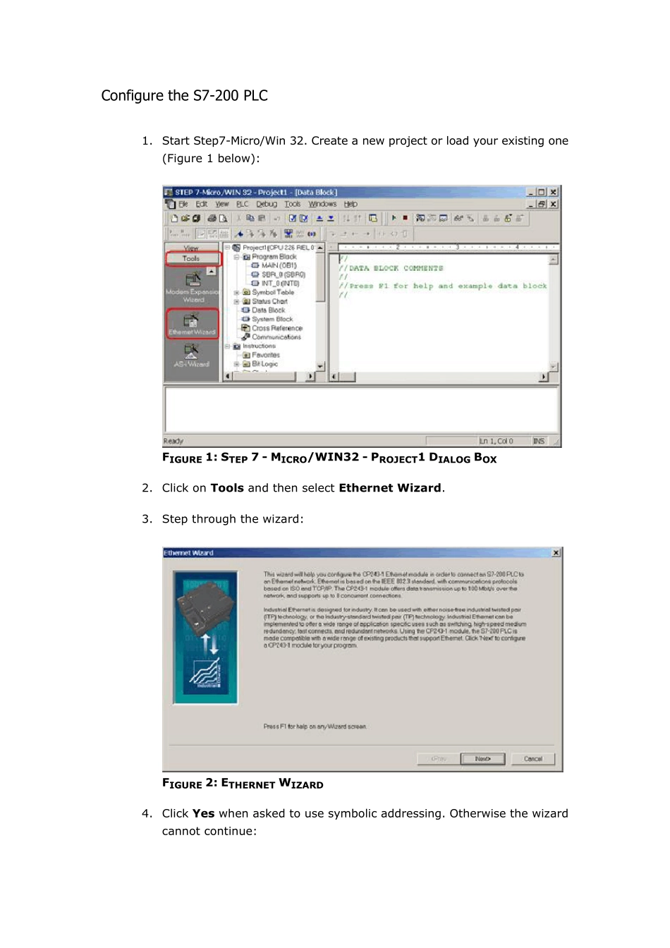
Start Step7-Micro/Win 32. Create a new project or load your existing one (Figure 1 below): FIGURE 1: STEP 7 - MICRO/WIN32 - PROJECT1 DIALOG BOX 2. Click on Tools and then select Ethernet Wizard. 3. Step through the wizard: FIGURE 2: ETHERNET WIZARD 4. Click Yes when asked to use symbolic addressing. Otherwise the wizard cannot continue: FIGURE 3: CLICK YES 5. 
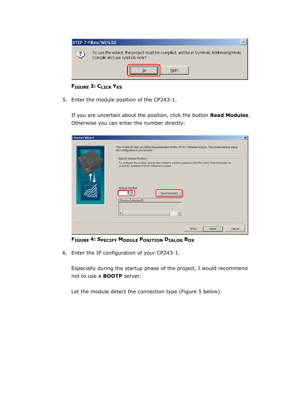
Enter the module position of the CP243-1. If you are uncertain about the position, click the button Read Modules. Otherwise you can enter the number directly: FIGURE 4: SPECIFY MODULE POSITION DIALOG BOX 6. 
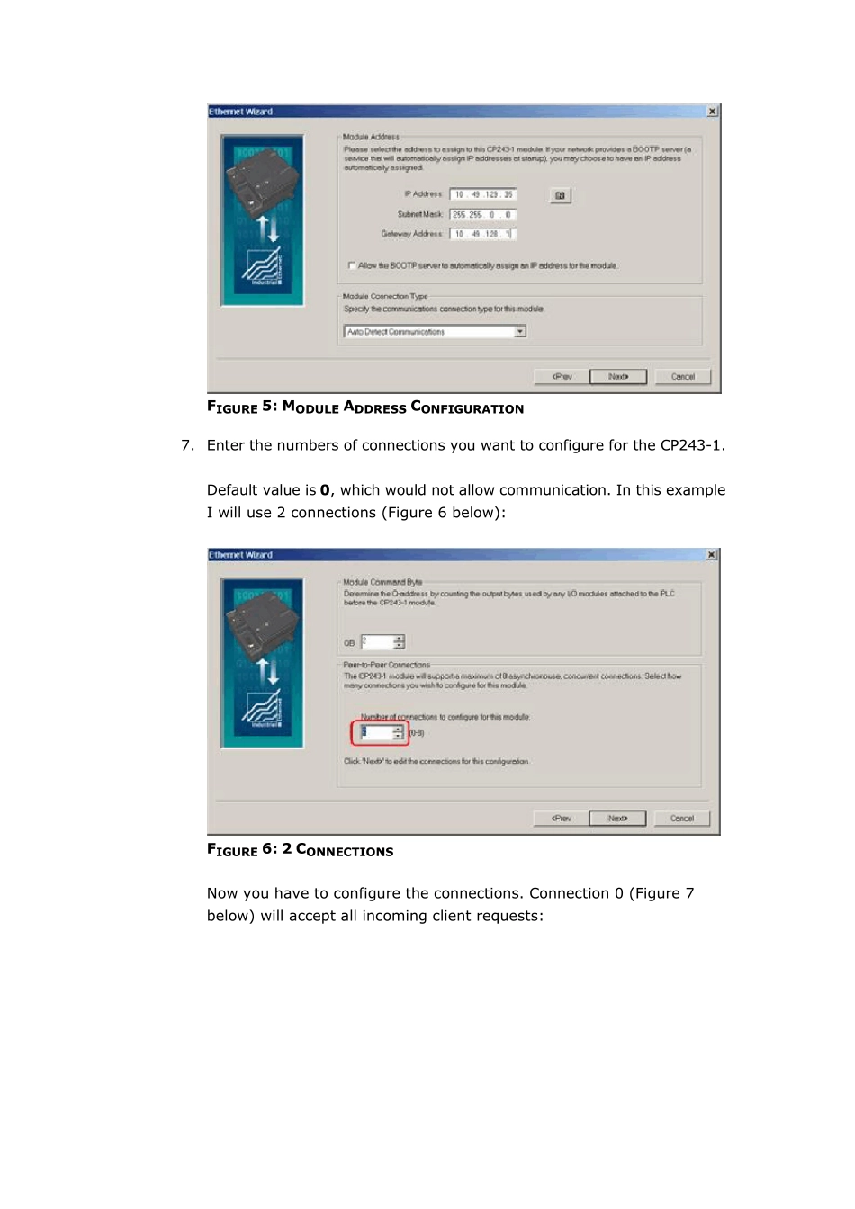
Enter the IP configuration of your CP243-1. Especially during the startup phase of the project, I would recommend not to use a BOOTP server. Let the module detect the connection type (Figure 5 below): FIGURE 5: MODULE ADDRESS CONFIGURATION 7. Enter the numbers of connections you want to configure for the CP243-1. Default value is 0, which would not allow communication. In this example I will use 2 connections (Figure 6 below): FIGURE 6: 2 CONNECTIONS Now you have to configure the connections. Connection 0 (Figure 7 below) will accept all incoming client requests: FIGURE 7: CONNECTION CONFIGURATION 8. Always select This is a Server Connection. I recommend using the default TSAP's as suggested by Step7-Micro/Win32. 9. Click Next Connection (or Prev. Connection if available) to step through all the connections to configure them. Note: If you plan to use such a connection, be sure that only one client tries to connect to the PLC via this connection at the same time. All other connection tries will be rejected. Connection 1 accepts only requests from the specified client: FIGURE 8: SPECIFIED CLIENT REQU...