电脑桌面
添加小米粒文库到电脑桌面
安装后可以在桌面快捷访问

Bladegen之叶片泵叶片建模

Bladegen之叶片泵叶片建模_第1页
1/20
Bladegen之叶片泵叶片建模_第2页
2/20
Bladegen之叶片泵叶片建模_第3页
3/20
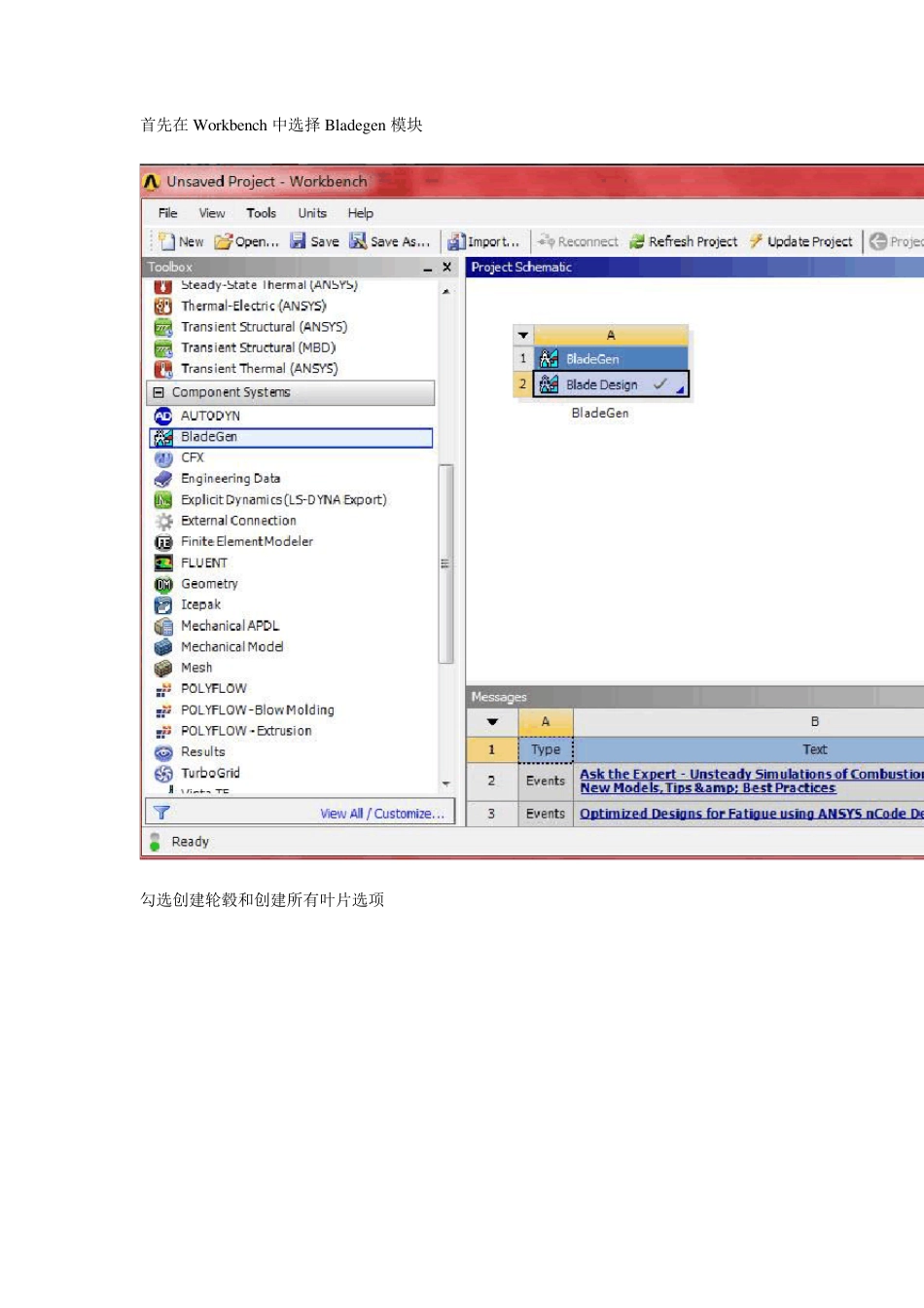
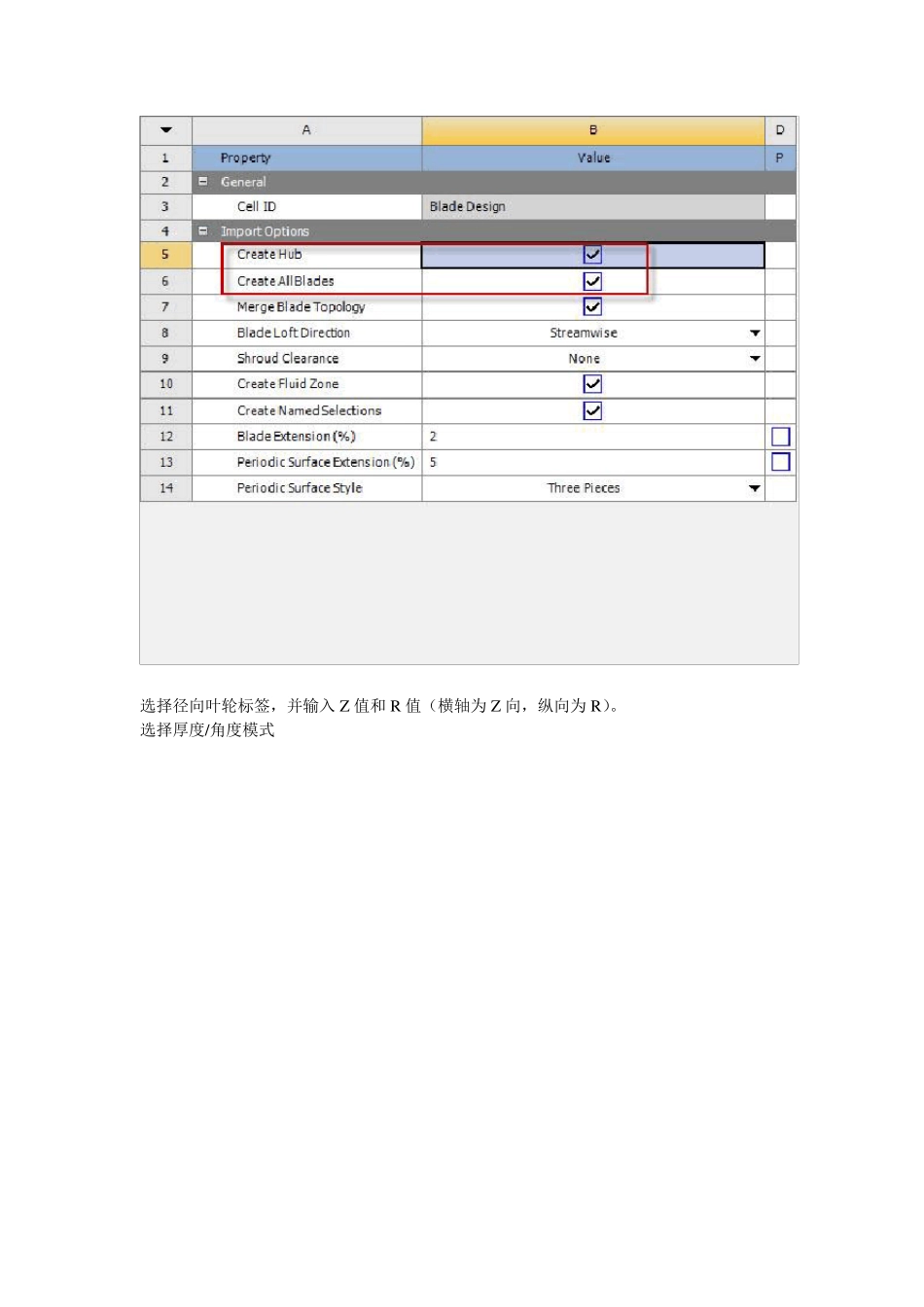
首先在Workbench 中选择 Bladegen 模块 勾选创建轮毂和创建所有叶片选项 选择径向叶轮标签,并输入Z 值和R 值(横轴为Z 向,纵向为R)。 
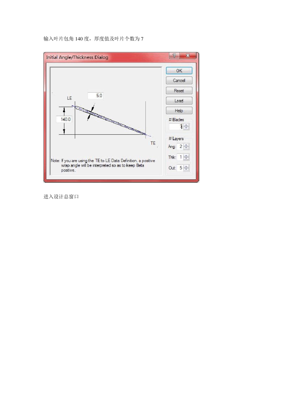
选择厚度/角度模式 输入叶片包角1 4 0 度,厚度值及叶片个数为 7 进入设计总窗口 The most critical operation in the meridional view is to define the shape of the hub and shroud curve. The endpoints for these curves were specified when Initial Design Parameters were entered in the Initial Meridional configuration dialog. The hub and shroud profile for this case are well defined automatically. In this case, there is no need for any additional modificati**. 意思是轮毂和轮缘(套罩)形状的定义在子午面上很关键,我们在 前面初始化子午面结构参数已定义了这些曲线的终点。 它们的其它轮廓由系统自动生成,不需要修改。用户可以通过改变坐标值及曲线特性进行修改。 双击各点修改坐标值来定义进口和出口截面 1. Double click the shroud inlet point at the top left of the meridional view. 2. The Point Location Dialog will open. The Horizontal value is the Axial location (Z co-ordinate) and the Vertical value represents the Radius. 3. Enter -10 and 110 for the horizontal and vertical values. Click OK. 4. Double click the hub inlet point (bottom left corner) and enter -10 and 25 for the horizontal and vertical values. Click OK. 5. Double click the hub outlet point (top right corner) and enter 91 and 250 for the horizontal and vertical values. Click OK. 6. Double click the shroud outlet point (top left corner) and enter 63 and 250 for the horizontal and vertical values. Click OK. 查看叶片角度视图,默认激活层为 hu b lay er,如图红点所示 注意到纵坐标变化范围为 140,即先前设置叶片包角值 在角度视图右键选择调整叶片角度 前缘 尾缘 Theta 曲线自动转成带有六个控制点的 Bez ier segment 同理进入shroud layer,修改角度 定义叶片厚度轮廓,切换到hu b lay er 定义三个点,并输入各厚度 z oom to fit 调整视图显示 通过五个点来调整抛物厚度曲线,再八个点来调整 激活shroud layer,会发现厚度和hub layer 是一样的 选择叶片属性定义椭圆角 生成模型,大功告成!!

1、当您付费下载文档后,您只拥有了使用权限,并不意味着购买了版权,文档只能用于自身使用,不得用于其他商业用途(如 [转卖]进行直接盈利或[编辑后售卖]进行间接盈利)。
2、本站所有内容均由合作方或网友上传,本站不对文档的完整性、权威性及其观点立场正确性做任何保证或承诺!文档内容仅供研究参考,付费前请自行鉴别。
3、如文档内容存在违规,或者侵犯商业秘密、侵犯著作权等,请点击“违规举报”。

碎片内容

Bladegen之叶片泵叶片建模

确认删除?
VIP
微信客服
  • 扫码咨询
会员Q群
  • 会员专属群点击这里加入QQ群
客服邮箱
回到顶部