外文出处:Design of PWM Controller in a MCS-51 Compatible MCU附件 2:外文原文(复印件)Design of PWM Controller in a MCS-51 Compatible MCU IntroductionPWM technology is a kind of voltage regulation method by controlling the switch frequency of DC power with fixed voltage to modify the two-end voltage of load. This technology can be used for a variety of applications including motor control, temperature control and pressure control and so on. 
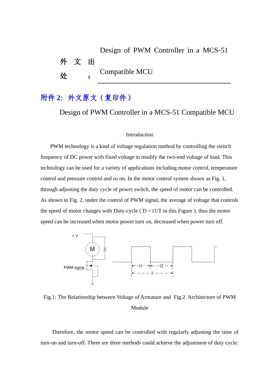
In the motor control system shown as Fig. 1, through adjusting the duty cycle of power switch, the speed of motor can be controlled. As shown in Fig. 2, under the control of PWM signal, the average of voltage that controls the speed of motor changes with Duty-cycle ( D = t1/T in this Figure ), thus the motor speed can be increased when motor power turn on, decreased when power turn off.Fig.1: The Relationship between Voltage of Armature and Fig.2 Architecture of PWM Module Therefore, the motor speed can be controlled with regularly adjusting the time of turn-on and turn-off. There are three methods could achieve the adjustment of duty cycle: (1) Adjust frequency with fixed pulse-width. (2) Adjust both frequency and pulse-width. (3) Adjust pulse-width with fixed frequency. Generally, there are four methods to generate the PWM signals as the following: (1) Generated by the device composed of separate logic components. This method is the original method which now has been discarded. (2) Generated by software. This method need CPU to continuously operate instructions to control I/O pins for generating PWM output signals, so that CPU can not do anything other. Therefore, the method also has been discarded gradually. (3) Generated by ASIC. The ASIC makes a decre...