Rev. 1.1 12/03Copyright © 2003 by Silicon LaboratoriesAN124-DS11AN124PIN SHARING TECHNIQUES FOR THE C2 INTERFACERelevant DevicesThis application note applies to the follow ing devices:C8051F300, C8051F301, C8051F302, and C8051F303.IntroductionC8051F30x devices include an on-chip SiliconLabs 2-Wire (C2) Interface for in-system program-ming, debugging, and boundary scan testing. Twosignals are associated with the C2 Interface: C2Clock (C2CK) and C2 Data (C2D). To preservepackage pins, the C2CK and C2D pins also func-tion as the user pins /RST and P0.7, respectively.
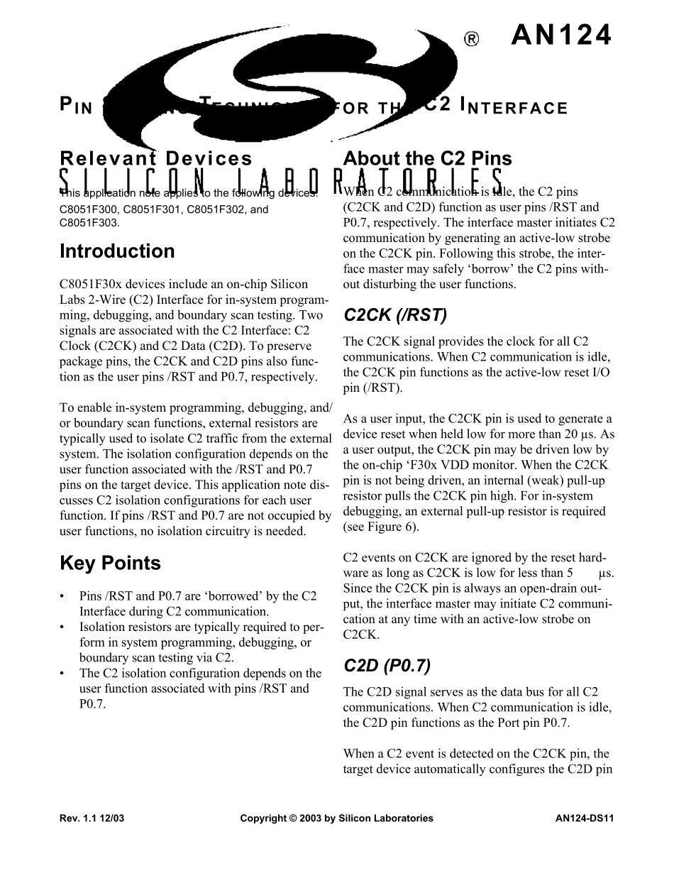
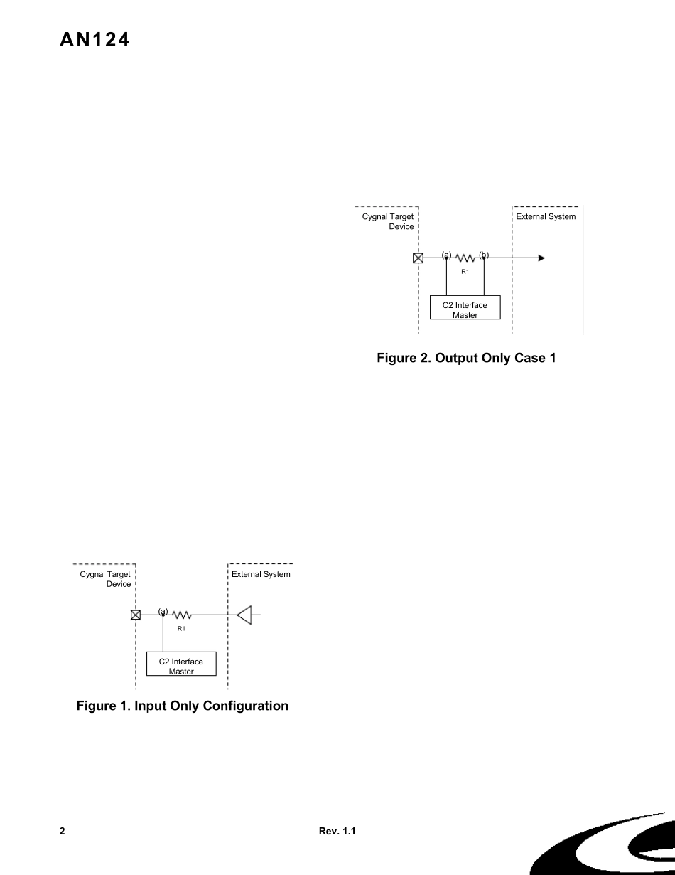
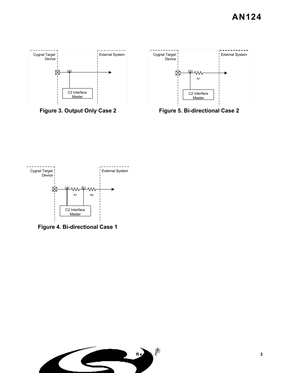
To enable in-system programming, debugging, and/or boundary scan functions, external resistors aretypically used to isolate C2 traffic from the externalsystem. The isolation configuration depends on theuser function associated with the /RST and P0.7pins on the target device. This application note dis-cusses C2 isolation configurations for each userfunction. If pins /RST and P0.7 are not occupied byuser functions, no isolation circuitry is needed.Key Points•Pins /RST and P0.7 are ‘borrowed’ by the C2 Interface during C2 communication.•Isolation resistors are typically required to per-form in system programming, debugging, or boundary scan testing via C2.•The C2 isolation configuration depends on the user function associated with pins /RST and P0.7.About the C2 PinsWhen C2 communication is idle, the C2 pins(C2CK and C2D) function as user pins /RST andP0.7, respectively. The interface master initiates C2communication by generating an active-low strobeon the C2CK pin. Following this strobe, the inter-face master may safely ‘borrow’ the C2 pins with-out disturbing the user functions. C2CK (/RST)The C2CK signal provides the clock for all C2communications. When C2 comm...