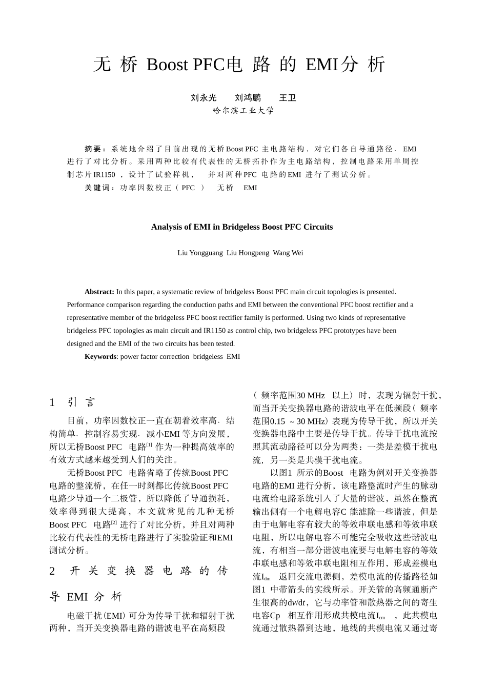
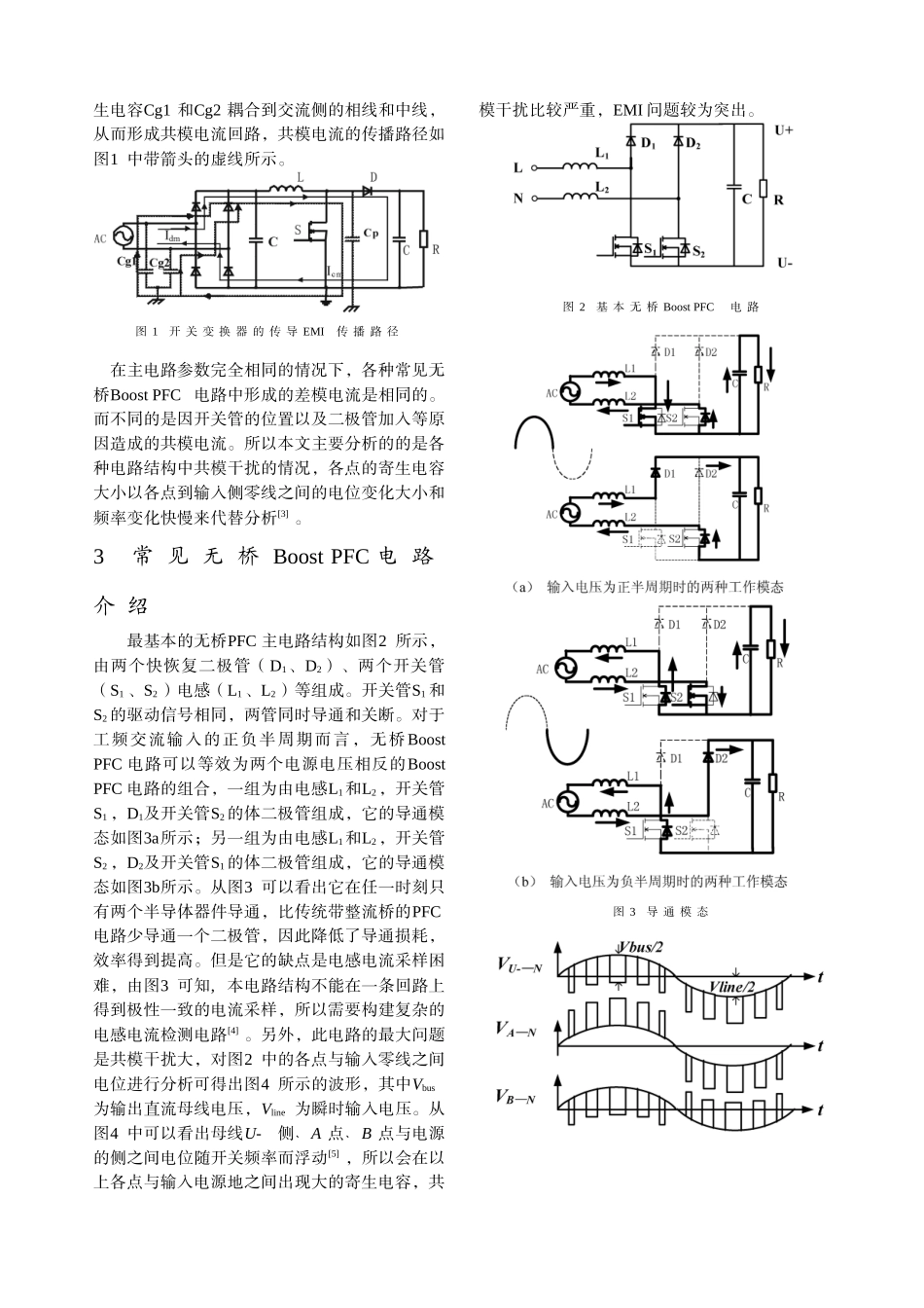
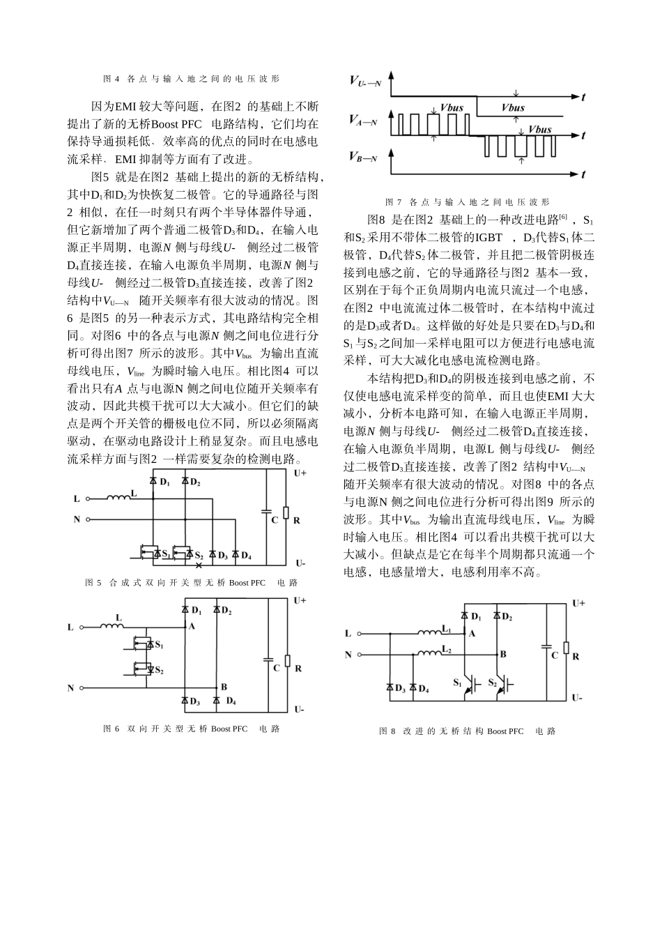
无 桥 Boost PFC电 路 的 EMI分 析刘永光 刘鸿鹏 王卫哈尔滨工业大学摘 要 : 系 统 地 介 绍 了 目 前 出 现 的 无 桥 Boost PFC 主 电 路 结 构 , 对 它 们 各 自 导 通 路 径 ﹑ EMI进 行 了 对 比 分 析 。 采 用 两 种 比 较 有 代 表 性 的 无 桥 拓 扑 作 为 主 电 路 结 构 , 控 制 电 路 采 用 单 周 控制 芯 片 IR1150 , 设 计 了 试 验 样 机 , 并 对 两 种 PFC 电 路 的 EMI 进 行 了 测 试 分 析 。关 键 词 : 功 率 因 数 校 正 ( PFC ) 无 桥 EMIAnalysis of EMI in Bridgeless Boost PFC CircuitsLiu Yongguang Liu Hongpeng Wang WeiAbstract: In this paper, a systematic review of bridgeless Boost PFC main circuit topologies is presented. Performance comparison regarding the conduction paths and EMI between the conventional PFC boost rectifier and a representative member of the bridgeless PFC boost rectifier family is performed. Using two kinds of representative bridgeless PFC topologies as main circuit and IR1150 as control chip, two bridgeless PFC prototypes have been designed and the EMI of the two circuits has been tested.Keywords: power factor correction bridgeless EMI1 引 言目前,功率因数校正一直在朝着效率高结﹑构简单控制容易实现﹑﹑减小EMI 等方向发展,所以无桥Boost PFC 电路[1] 作为一种提高效率的有效方式越来越受到人们的关注。无桥Boost PFC 电路省略了传统Boost PFC电路的整流桥,在任一时刻都比传统Boost PFC电路少导通一个二极管,所以降低了导通损耗,效率得到很大提高,本文就常见的几种无桥Boost PFC 电路[2] 进行了对比分析,并且对两种比较有代表性的无桥电路进行了实验验证和EMI测试分析。2 开 关 变 换 器 电 路 的 传导 EMI 分 析电磁干扰(EMI) 可分为传导干扰和辐射干扰两种,当开关变换器电路的谐波电平在高频段( 频率范围30 MHz以上) 时,表现为辐射干扰,而当开关变换器电路的谐波电平在低频段( 频率范围0.15 ~30 MHz) 表现为传导干扰,所以开关变换器电路中主要是...


