23. 模拟计算器数字输入及显示 1. 实验任务 (1. 开机时,显示“0” (2. 第一次按下时,显示“D1”;第二次按下时,显示“D1D2”;第三按下时,显示“D1D2D3”,8 个全显示完毕,再按下按键下时,给出“嘀”提示音
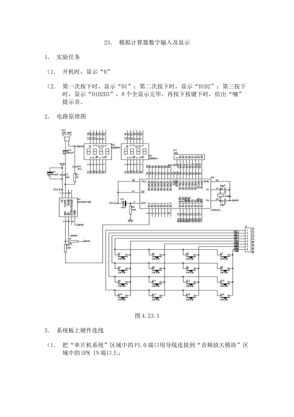
2. 电路原理图 图 4
1 3. 系统板上硬件连线 (1. 把“单片机系统”区域中的 P1
0 端口用导线连接到“音频放大模块”区域中的 SPK IN 端口上; (2. 把“单片机系统“区域中的 P3
7 端口用 8 芯排线连接到“4X4 行列式键盘”区域中的 C1-C4 R1-R4 端口上; (3. 把“单片机系统”区域中的 P0
7 端口用 8 芯排线连接到“动态数码显示”区域中的 A-H 端口上; (4. 把“单片机系统:区域中的 P2
7 端口用 8 芯排线连接到“动态数码显示”区域中的 S1-S8 端口上; 4. 相关程序设计内容 (1. 行列式键盘输入及按键功能设定; (2. 动态数码显示; (3. 数码显示方式处理;5. 汇编源程序(略)6. C 语言源程序#include unsigned char code dispcode[]={0x3f,0x06,0x5b,0x4f,0x66,0x6d,0x7d,0x07,0x7f,0x6f,0x77,0x7c,0x39,0x5e,0x79,0x71,0x00};unsigned char code dispbitcode[]={0xfe,0xfd,0xfb,0xf7,0xef,0xdf,0xbf,0x7f};unsigned char dispbuf[8]={0,16,16,16,16,16,16,16};unsigned char dispbitcount;unsigned char temp;unsigned char i,j;unsigned