1 Application Note Title: Layout Guidelines of IT7250/ 7260 Part No
: IT7250/7260 Chip Ver: BX Doc No
: ITAE-AN-09-1-09 Doc Ver: V1
0 Date: June 25, 2010 Confidential Table of Contents 1 IT7250/7260 FPC/PCB Layout Guidelines… … … … … … … … … … … … … … …
1 Reference circuit… … … … … … … … … … … … … … … … … … … … … … … … … 2 1
2 Layout guidelines… … … … … … … … … … … … … … … … … … … … … … … …
3 2 IT7250/IT7260 ITO Layout Guidelines… … … … … … … … … … … … … … … … … …
sensor traces and shield signal layout… … … … … … … … … … … … …
2 IT7250/IT7260 Support Three Types of ITO sensors… … … … … … … …
3 ITO with button format… … … … … … … … … … … … … … … … … … … … … …
17 2 1
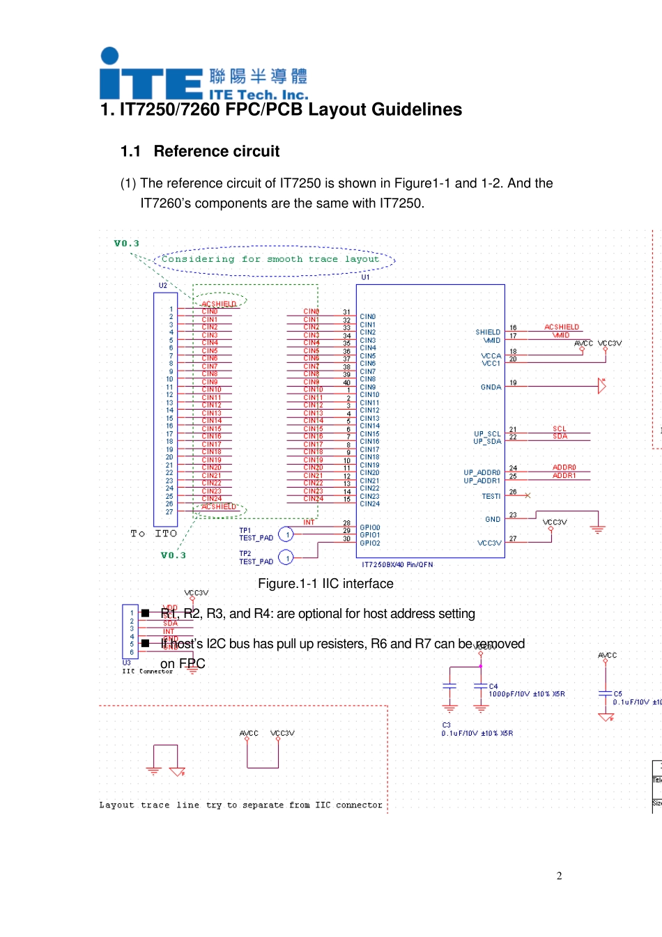
IT7250/7260 FPC/PCB Layout Guidelines 1
1 Reference circuit (1) The reference circui