EileEdit 土 iciwUHplayDiagram5'niulfitionflHalyshScl 亡 TookH^P网询吕罷◎▼圉|網㈤ UA上釦巫nniLn低压开关及控制实验目的:1. 掌握高压断路器和低压开关的区别。2. 熟练运用 MATLAB 中的电力系统工具箱对理想低压开关电路进行建模,观察分析其波形
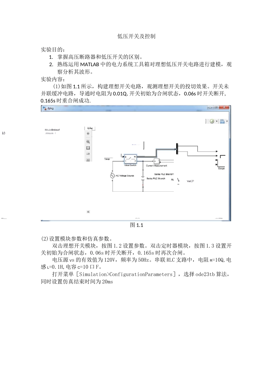
。实验内容:(1)如图 1.1 所示,构建理想开关电路,观测理想开关的投切效果。开关未并联缓冲电路,导通时电阻为 0.01Q,开关初始为合闸状态,0.06s 时开关断开,0.165s 时重合闸成功.图 1.1(2)设置模块参数和仿真参数。双击理想开关模块,按图 1.2 设置参数。双击定时器模块,按图 1.3 设置开关初始为合闸状态,0.06s 时开关断开,0.165s 时再次合闸。
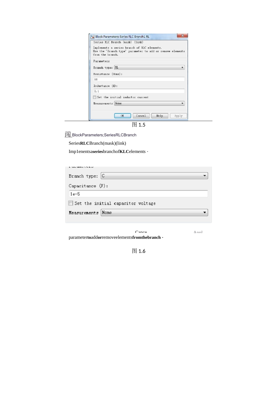
电压源 Vs 的有效值为 120V,频率为 50Hz。串联 RLC 支路中,电阻 R=10Q,电感 L=0.1H,电容 C=10 口 F。打开菜单[Simulation>ConfigurationParameters],选择 ode23tb 算法,同时设置仿真结束时间为 20msVati 沪kleahJianrr-il□IMUJAIBrdvs«t'-冋詁宓「RjeeIDOcde23tb「V了片p-Cdriinuou图 1.2r| 牛 | SourceBlockParairretcrffiTimerTimer(inaski(liiLklCenerates 注signalchangingstspecifiEdtines.IfasignalvalueisnotspecifiedattLTLBserojIheoutpuliskep-!:at0uritilthefirstspecified"trmsilicintLTLC.ParametersTime(s):[00.06D.165]Amplitude:7ToijOECancelHelpApply图 1.3I 怡 BlockPararnct-rryACSource图 1.4OKCanceHelpAppl图 1.5闯 BlockParameters;SeriesRLCBranchSeriesRLCBranch(mask)(link)Imp1enentsaseriesbranchofKLCelements・Usethe!Branchtype!parametertoaddorremoveelementsfromthebranch・图 1.6MMAppl三相电压电流测量模块图 3.3回 BlockParameters:Three-PhaseV-IMeasurementThree-PhaseVIJileas 口匸 EITLerrt(nask)(link)Idealthree-phasevoItageand.currentmeasureinents・Theblockc:ii_Loutputthevoltagesandcurrentsinpermiitvaluesorinvo1+s:iLrud:ajiLperes・图 3.3输电线路图 3.4:也 BlockParameters:Diwt「ibut 亡dParameturaLinel~eitherspecifycouplets~[JfsN]matricesat-sinplyeniersequence~parametersvectors:thepositiveandzerosequenceuarametersforatvrcr^haseorthree-phasetransposedline,rlustheniutualsero-sequencelorasis-phasetransposedline(2coupled3-phaseliries.).ParajnetersWiuiberofphases[If]:Frequencyusedforrlcspec...