SignalTap IIw ith Verilog Designs1Introdu ctionThis tutorial explains how to use the SignalTap II feature within Altera’s Quartus ® II software. The SignalTap IIEmbedded Logic Analyzeris a system-level debugging tool that captures and displays signals in circuits designedfor implementation in Altera’s FPGAs.
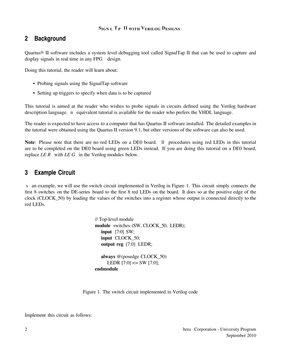
Contents:•Example Circuit•Using the SignalTap II Logic Analyzer•Probing the Design Using SignalTap•Advanced Trigger Options•Sample Depth and Buffer Acquisition ModesAltera Corporation - University ProgramSeptember 20101SIGNAL TAP II WITH VERILOG DESIGNS2BackgroundQuartus® II software includes a system level debugging tool called SignalTap II that can be used to capture anddisplay signals in real time in any FPGA design.Doing this tutorial, the reader will learn about:• Probing signals using the SignalTap software• Setting up triggers to specify when data is to be capturedThis tutorial is aimed at the reader who wishes to probe signals in circuits defi ned using the Verilog hardwaredescription language. An equivalent tutorial is available for the reader who prefers the VHDL language.The reader is expected to have access to a computer that has Quartus II software installed. The detailed examples inthe tutorial were obtained using the Quartus II version 9.1, but other versions of the software can also be used.Note: Please note that there are no red LEDs on a DE0 board. Allprocedures using red LEDs in this tutorialare to be completed on the DE0 board using green LEDs instead. If you are doing this tutorial on a DE0 board,replace LEDR with LEDG in the Verilog modules below.3Example CircuitAs an example, we will use the switch circuit implemented in Verilog in Figure 1. This circuit simply connects thef...