SS12-S100SS12-S100, Rev. A1SS12 - S1001.
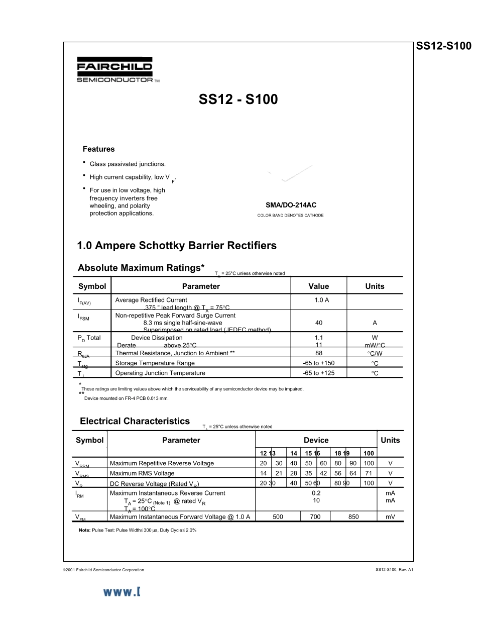
0 Ampere Schottky Barrier RectifiersAbsolute Maximum Ratings* TA = 25°C unless otherwise noted*These ratings are limiting values above which the serviceability of any semiconductor device may be impaired.**Device mounted on FR-4 PCB 0.013 mm.Electrical Characteristics TA = 25°C unless otherwise noted2001 Fairchild Semiconductor CorporationFeatures• Glass passivated junctions.• High current capability, low VF.• For use in low voltage, highfrequency inverters freewheeling, and polarityprotection applications.SMA/DO-214AC COLOR BAND DENOTES CATHODE Symbol Parameter Value Units IF(AV) Average Rectified Current .375 " lead length @ TA = 75°C 1.0 A IFSM Non-repetitive Peak Forward Surge Current 8.3 ms single half-sine-wave Superimposed on rated load (JEDEC method) 40 A PD Total Device Dissipation Derate above 25°C 1.1 11 W mW/°C RθJA Thermal Resistance, Junction to Ambient ** 88 °C/W Tstg Storage Temperature Range -65 to +150 °C TJ Operating Junction Temperature -65 to +125 °C Symbol Parameter Device Units 12 13 14 15 16 18 19 100 VRRM Maximum Repetitive Reverse Voltage 20 30 40 50 60 80 90 100 V VRMS Maximum RMS Voltage 14 21 28 35 42 56 64 71 V VR DC Reverse Voltage (Rated VR) 20 30 40 50 60 80 90 100 V IRM Maximum Instantaneous Reverse Current TA = 25°C (Note 1) @ rated VR TA = 100°C 0.2 10 mA mA VFM Maximum Instantaneous Forward Voltage @ 1.0 A 500 700 850 mV Note: Pulse Test: Pulse Width ≤ 300 µs, Duty Cycle ≤ 2.0%SS12-S100SS12-S100, Rev. A1Schottky Barrier Rectifiers(continued)Typical CharacteristicsForward Current Derating Curve02040608010012014000.250.50.751LEAD TEMPERATURE ( C)FORWARD CURRENT (A)ºSINGLE PHASEHALF WAVE60HzRESISTIVE ORINDUCTIVE LOADP....