复合材料Abaqus 仿真分析——精讲版 本文以一个非常简单的复合材料层合板为例,应用Abaqus/CAE 对其进行线性静态分析。一块边长为254mm 的方形两层层合板,两层厚度均为2.54mm,第一层铺层角45°,第二层铺层角-45°;板的四边完全固支,板的上表面受到 689.4kpa 的压强。
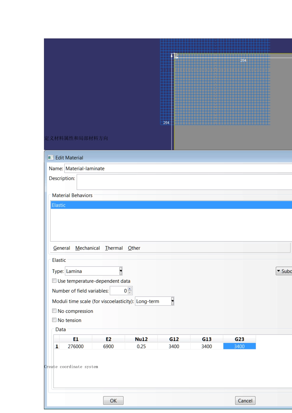
各单层的材料相同,材料属性如下:E1=276GPa,E2=6.9GPa,E3=5.2GPa,γ12=0.25,G12=3.4GPa,G13=3.4GPa,G23=3.4G。 
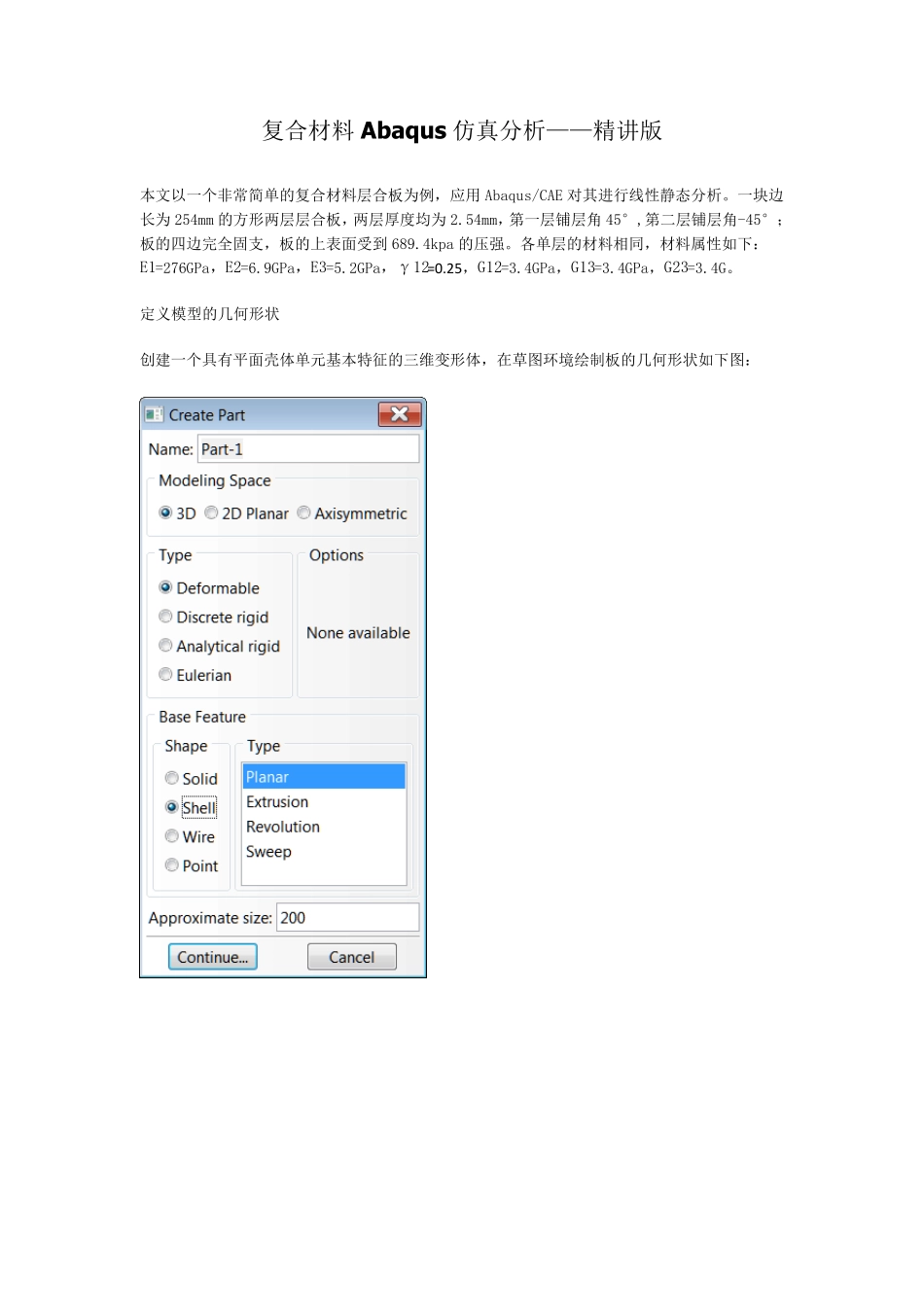
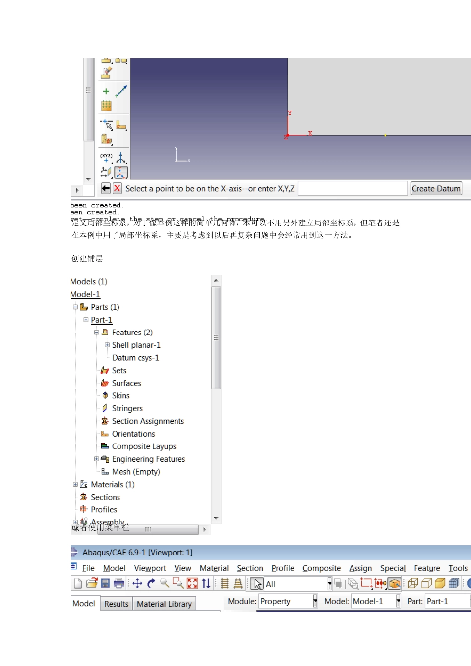
定义模型的几何形状 创建一个具有平面壳体单元基本特征的三维变形体,在草图环境绘制板的几何形状如下图: 定义材料属性和局部材料方向 Create coordinate system 定义局部坐标系,对于像本例这样的简单几何体,本可以不用另外建立局部坐标系,但笔者还是在本例中用了局部坐标系,主要是考虑到以后再复杂问题中会经常用到这一方法。 创建铺层 或者使用菜单栏 注意这三种单元类型的区别,详情请查看 此处使用全局坐标系 使用用户自定义坐标系 使用全局坐标系和局部坐标系的区别在下面这一步可以查看 如果使用全局坐标系,会有方向指示,如果使用用户自定义坐标系,在层中没有方向指示 可以通过’工具——查询’来检查铺层(Tool ---- Query----ply stack plot) Case 1 全局坐标系 Rotation angle depends on the coordinate system defined by user. Par example, if x-axe in the user defined system is parallel to the direction of fiber; we should replace the angles by 0 and 90. 使用局部坐标系 生成装配件、定义分析步和输出要求 此选项可以选择图中显示的数据 定义分析步,保留各项默认值即可。 场输出要求和历史输出要求都按默认的输出方式。 为了结果中能查看每个ply 的输出情况,应该在场输出中进行一些修改 历史输出默认值即可 (场输出field ou tpu t 和历史输出 history ou tpu t 的区别, refer to u ser’s manu al) 规定边界条件和施加载荷 (689.4 KPa and all edges : encastre ) 定义完边界条件和载荷后模型会有如下显示 划分网格和定义作业 定义单元类型S8R5( The differences of all element types should be clear for analysis) 划分 8X8 结构性网格 定义作业并检查提交求解 在作业管理器中,当状态显示成功后点击“结果”可直接进入结果可视化模块。 后处理 常用工具 Tool Display group Color code 查看各单层的应力 The difference of these two types of field output refer to manual Field output with the option ‘composite layer up’ Field output with the option ‘whole model’ Field output with the option ‘composite layer up’ This option is refer to section point u sed du ring analy sis. You can choose it in the part of field ou tpu t option Field output with the option ‘whole model’ Different active locations give different results