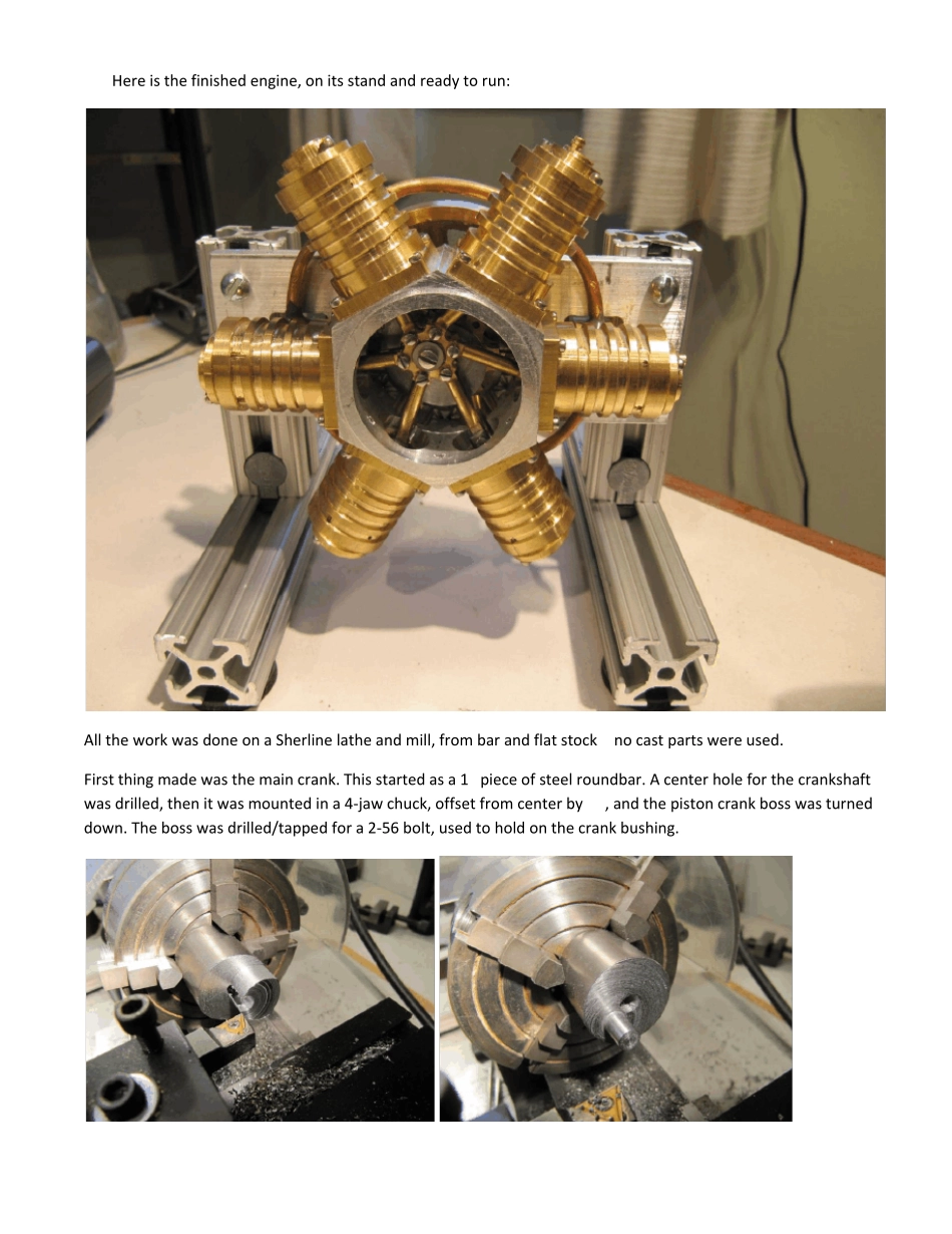
Here is the finished engine, on its stand and ready to run: All the work was done on a Sherline lathe and mill, from bar and flat stock – no cast parts were used. First thing made was the main crank. This started as a 1” piece of steel roundbar. A center hole for the crankshaft was drilled, then it was mounted in a 4-jaw chuck, offset from center by ¼”, and the piston crank boss was turned down. The boss was drilled/tapped for a 2-56 bolt, used to hold on the crank bushing. 
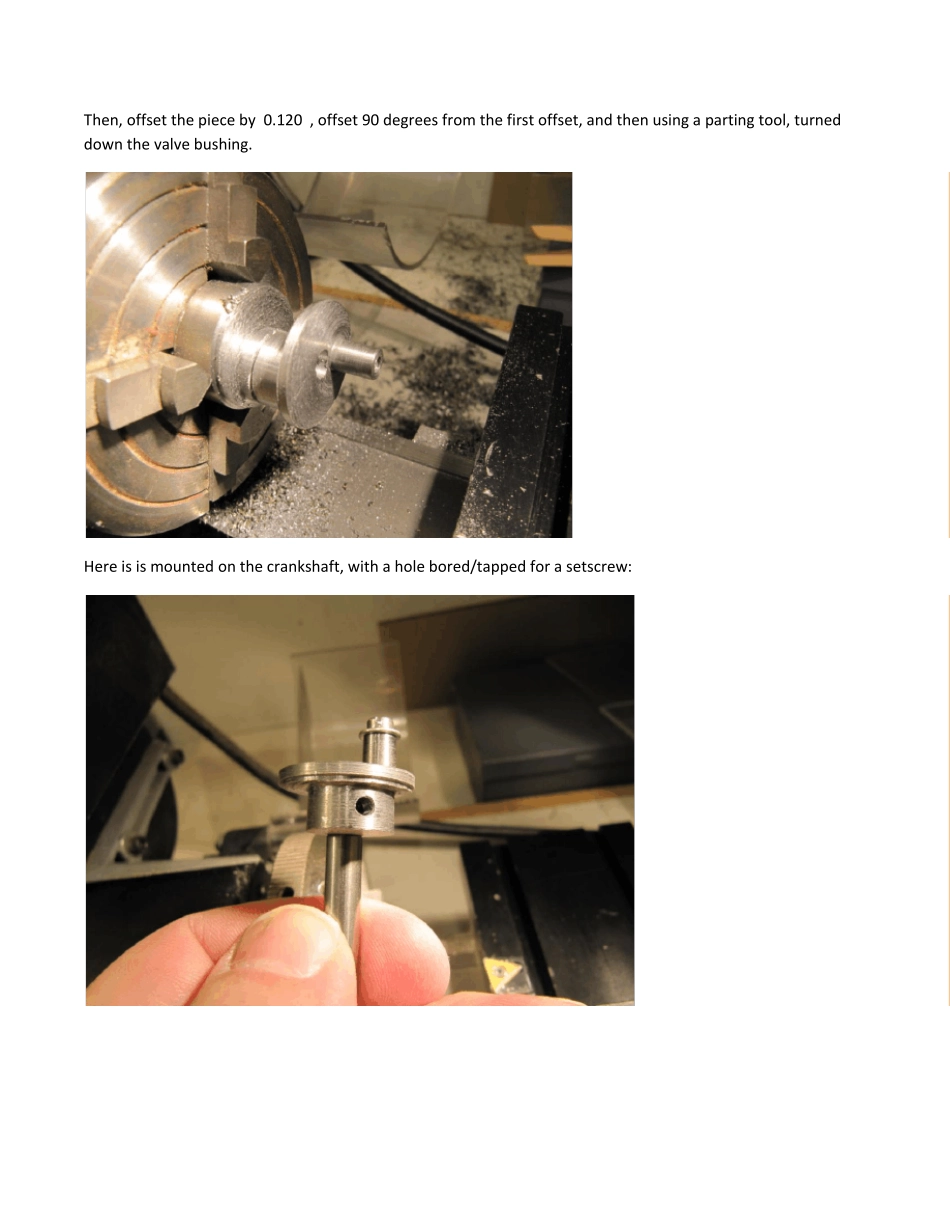
Then, offset the piece by 0.120”, offset 90 degrees from the first offset, and then using a parting tool, turned down the valve bushing. 
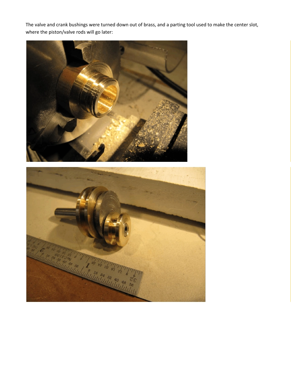
Here is is mounted on the crankshaft, with a hole bored/tapped for a setscrew: The valve and crank bushings w ere turned dow n out of brass, and a parting tool used to make the center slot, w here the piston/valve rods w ill go later: Then, the bushings were drilled/tapped for 2-56 bolts: For the number one cylinder, the rods are not pivotted, but are held in place perpendicular to the bushing. This makes the bushing track its rotation with that cylinder. Without this the bushing could over-rotate and jam up the connecting rods. As I understand it, this is a standard feature of all radial piston engines. Here, a hole is drilled to accept a post turned on the end of one of the connecting rods of the set of six. All the other rods are free to pivot. Next, to reduce the weight of the bushings (and also to make them look better!), half-rounds were milled between the bolts. Here is the number one rod, in place showing how it fits into the restraining hole: And all the rods test fitted (not cut to length yet) Next came a big milling job – getting the...