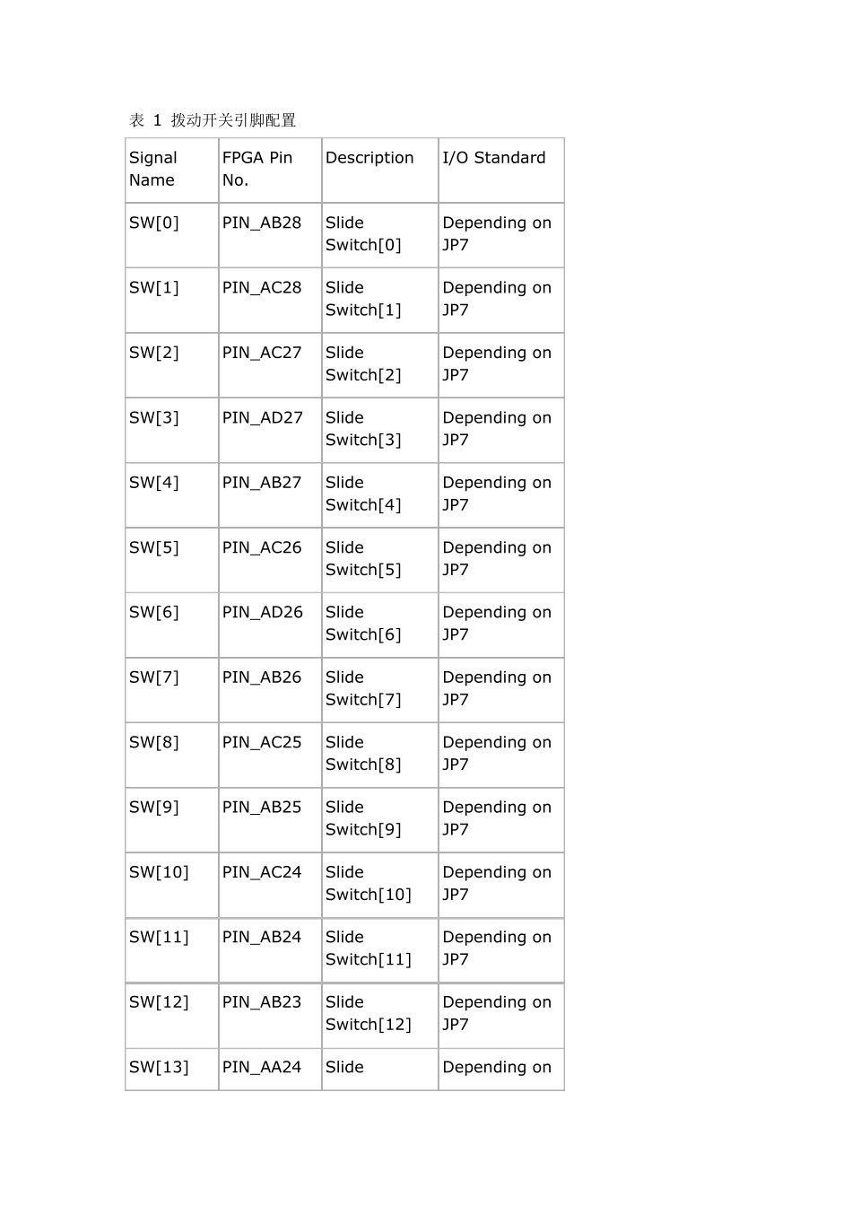
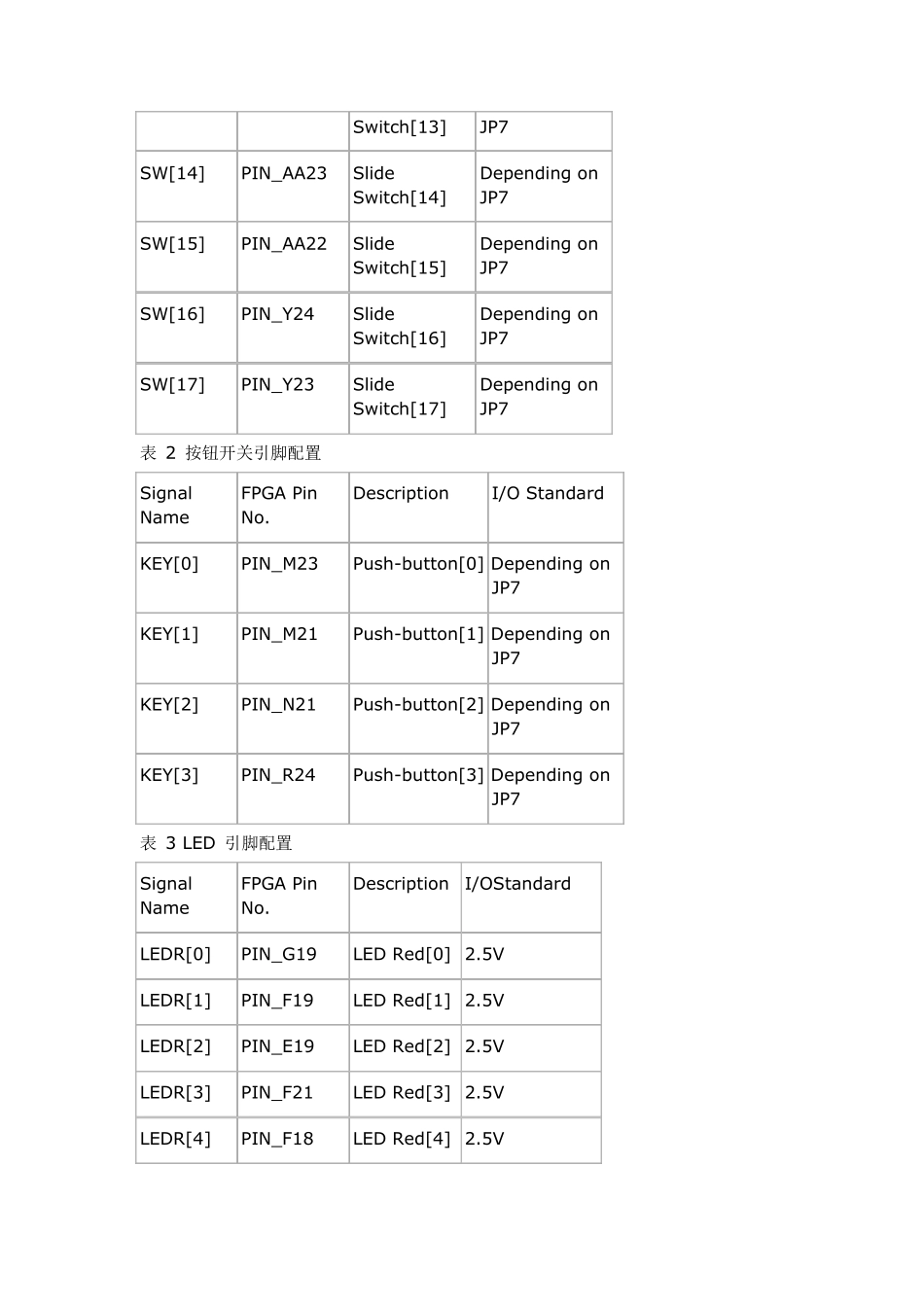
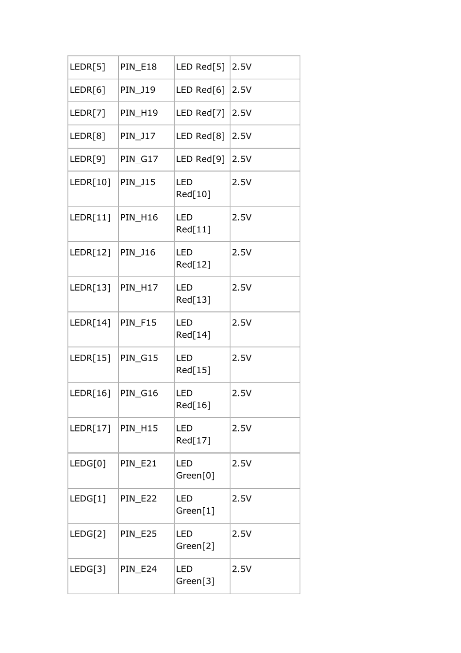
表 1 拨动开关引脚配置 Signal Name FPGA Pin No. Description I/O Standard SW[0] PIN_AB28 Slide Sw itch[0] Depending on JP7 SW[1] PIN_AC28 Slide Sw itch[1] Depending on JP7 SW[2] PIN_AC27 Slide Sw itch[2] Depending on JP7 SW[3] PIN_AD27 Slide Sw itch[3] Depending on JP7 SW[4] PIN_AB27 Slide Sw itch[4] Depending on JP7 SW[5] PIN_AC26 Slide Sw itch[5] Depending on JP7 SW[6] PIN_AD26 Slide Sw itch[6] Depending on JP7 SW[7] PIN_AB26 Slide Sw itch[7] Depending on JP7 SW[8] PIN_AC25 Slide Sw itch[8] Depending on JP7 SW[9] PIN_AB25 Slide Sw itch[9] Depending on JP7 SW[10] PIN_AC24 Slide Sw itch[10] Depending on JP7 SW[11] PIN_AB24 Slide Sw itch[11] Depending on JP7 SW[12] PIN_AB23 Slide Sw itch[12] Depending on JP7 SW[13] PIN_AA24 Slide Depending on Sw itch[13] JP7 SW[14] PIN_AA23 Slide Sw itch[14] Depending on JP7 SW[15] PIN_AA22 Slide Sw itch[15] Depending on JP7 SW[16] PIN_Y24 Slide Sw itch[16] Depending on JP7 SW[17] PIN_Y23 Slide Sw itch[17] Depending on JP7 表 2 按钮开关引脚配置 Signal Name FPGA Pin No. Description I/O Standard KEY[0] PIN_M23 Push-button[0] Depending on JP7 KEY[1] PIN_M21 Push-button[1] Depending on JP7 KEY[2] PIN_N21 Push-button[2] Depending on JP7 KEY[3] PIN_R24 Push-button[3] Depending on JP7 表 3 LED 引脚配置 Signal Name FPGA Pin No. Description I/OStandard LEDR[0] PIN_G19 LED Red[0] 2.5V LEDR[1] PIN_F19 LED Red[1] 2.5V LEDR[2] PIN_E19 LED Red[2] 2.5V LEDR[3] PIN_F21 LED Red[3] 2.5V LEDR[4] PIN_F18 LED Red[4] 2.5V LEDR[5] PIN_E18 LED Red[5] 2.5V LEDR[6] PIN_J19 LED Red[6] 2.5V LEDR[7] PIN_H19 LED Red[7] 2.5V LEDR[8] PIN_J17 LED Red[8] 2.5V LEDR[9] PIN_G17 LED Red[9] 2.5V LEDR[10] PIN_J15 LED Red[10] 2.5V LEDR[11] PIN_H16 LED Red[11] 2.5V LEDR[12] PIN_J16 LED Red[12] 2.5V LEDR[13] PIN_...