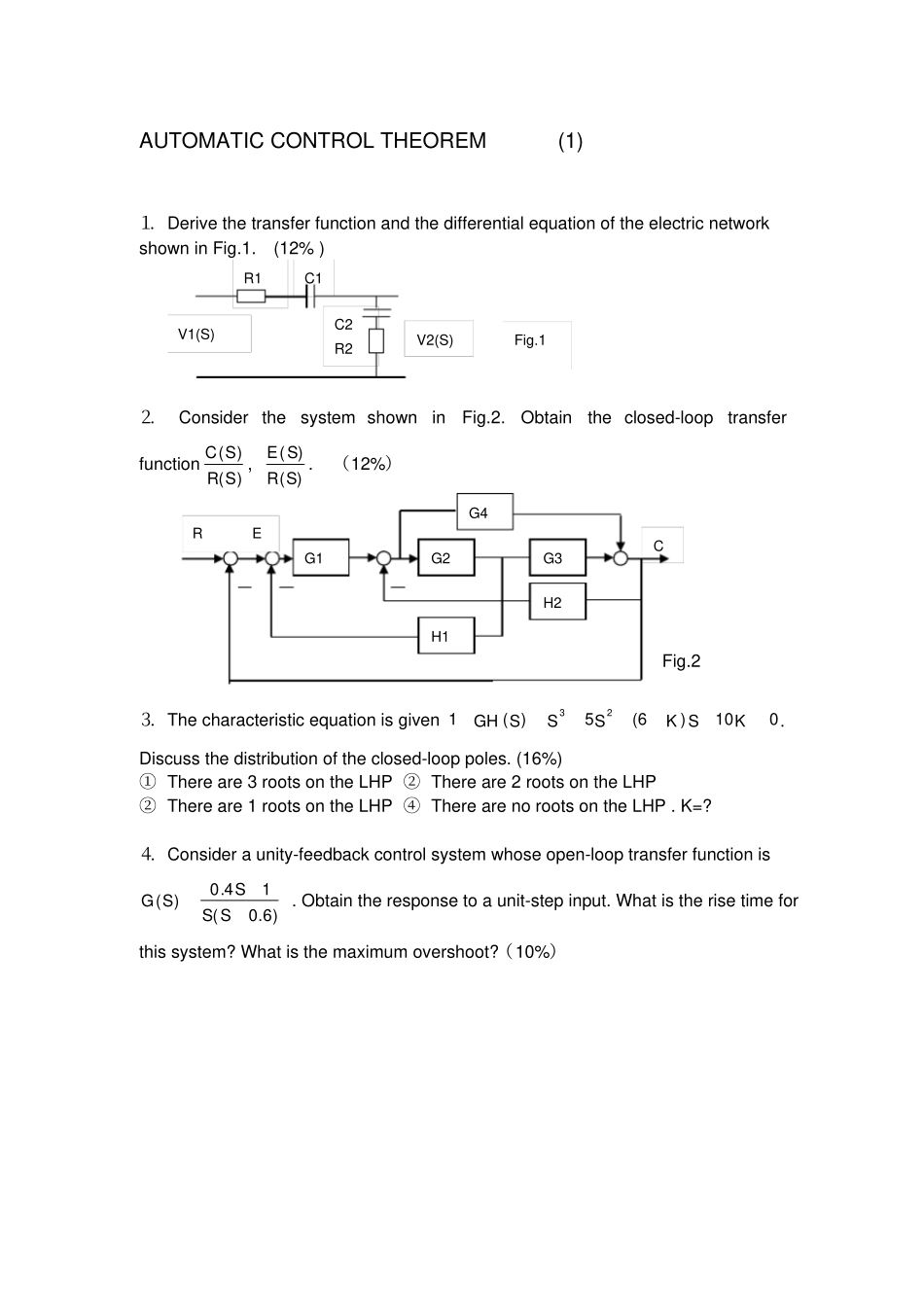
AUTOMATIC CONTROL THEOREM (1) ⒈ Derive the transfer function and the differential equation of the electric network shown in Fig
(12% ) ⒉Consider the system shown in Fig
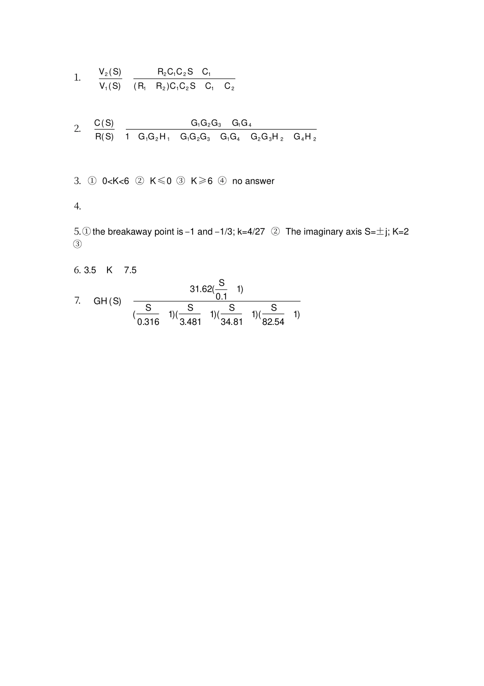
Obtain the closed-loop transfer function)()(SRSC, )()(SRSE
(12%)Fig
2 ⒊ The characteristic equation is given 010)6(5)(123KSKSSSGH
Discuss the distribution of the closed-loop poles
(16%) ① There are 3 roots on the LHP ② There are 2 roots on the LHP ② There are 1 roots on the LHP ④ There are no roots on the LHP
⒋ Consider a unity-feedback control system whose open-loop transfer function is )6
0)(SSSSG
Obtain the response to a unit-step input
What is the rise time for this system
What is the maximum overshoot
(10%)C G1 G2 G3 G4 H2 H1 R E C2 R2 V2(S) R1 C1 V1(S) Fig
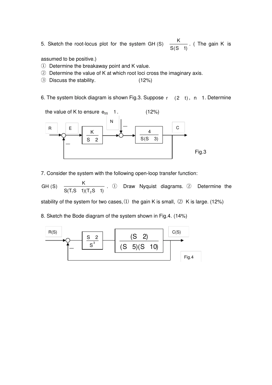
Sketch the root-locus plot for th