一、 实验目的 掌握 VHDL 程序设计方法 二、 实验内容和要求 共 6 个尾灯,汽车正常行驶时,6 个灯全灭; 左转时,左边 3 个灯从右到左依次亮灭; 右转时,右边 3 上灯从左到右依次亮灭; 刹车时,车灯全亮;故障时,全部闪烁。 在软件工具平台上,进行 VHDL 语言的各个模块编程输入、编译实现和仿真验证。 三、 实验仪器 计算机 四、 实验方法、步骤及结构测试 1.
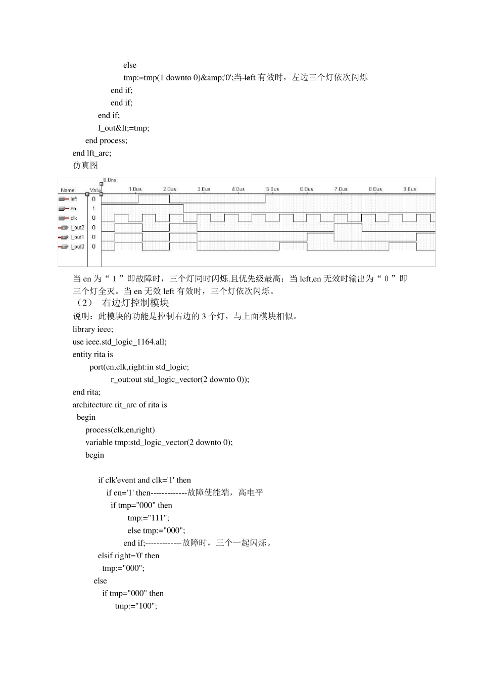
系统设计与方案: 根据系统设计要求,采用自顶向下设计方法,顶层设计采用原理图设计,它由主控模块、左边灯控制模块和右边灯控制模块三部分组成。 2.系统功能: 用 6 个发光管模拟 6 个汽车尾灯(左右各 3 个),用 4 个开关作为汽车控制信号,分别为:左拐、右拐、故障和刹车。4 个输入信号为: 3.参考 VHDL 源程序 (1) 主控制模块 说明:此程序为系统主控制模块。当左转时,lft 信号有效;右转时,rit 信号有效;当左右信号都有效的时,lr 有效。 library ieee; rit<='0'; use ieee.std_logic_1164.all; entity kz is port(left,right:in std_logic; lft,rit,lr:out std_logic); end kz; architecture kz_arc of kz is begin process(left,right) variable a:std_logic_vector(1 downto 0); begin a:=left&right; case a is when"00"=>lft<='0';----------正常 rit<='0'; lr<='0'; when"10"=>lft<='1';----------左转 lr<='0'; when"01"=>rit<='1';-----------右转 lft<='0'; lr<='0'; when others=>rit<='1';---------STOP lft<='1'; lr<='1'; end case; end process; end kz_arc; 当左右信号都有效时,输出为全“1” (2)左边灯控制模块 说明:此模块的功能是当左转时控制左边的 3 个灯, library ieee; use ieee.std_logic_1164.all; entity lfta is port(en,clk,left:in std_logic; l_out:out std_logic_vector( 2 downto 0)); end lfta; architecture lft_arc of lfta is begin process(clk,en,left) variable tmp:std_logic_vector(2 downto 0); begin if clk'event and clk='1' then if en='1' then------------------故障使能端,高电平有效 if tmp="000" then tmp:="111"; else tmp:="000"; end if;-------------------------en=’1’,故障,左边三个灯一起闪烁 elsif left='0' then tmp:="000"; ------------...