PADS LAYOUT 9
3(PADS2007 也可以参考通用步骤) 二、一般步骤 多层板的分割一般步骤为:定义叠层→设置层的属性(正、负片)→分配网络→分割→铺铜
首次定义多层板的叠层结构
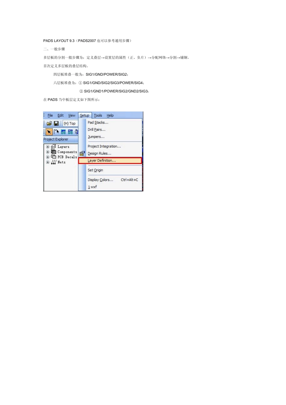
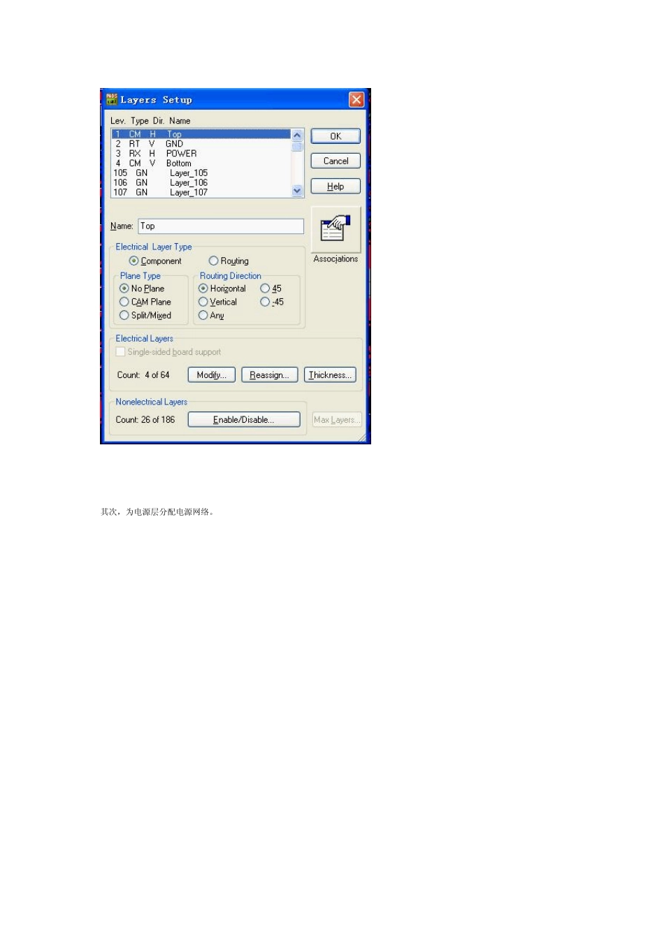
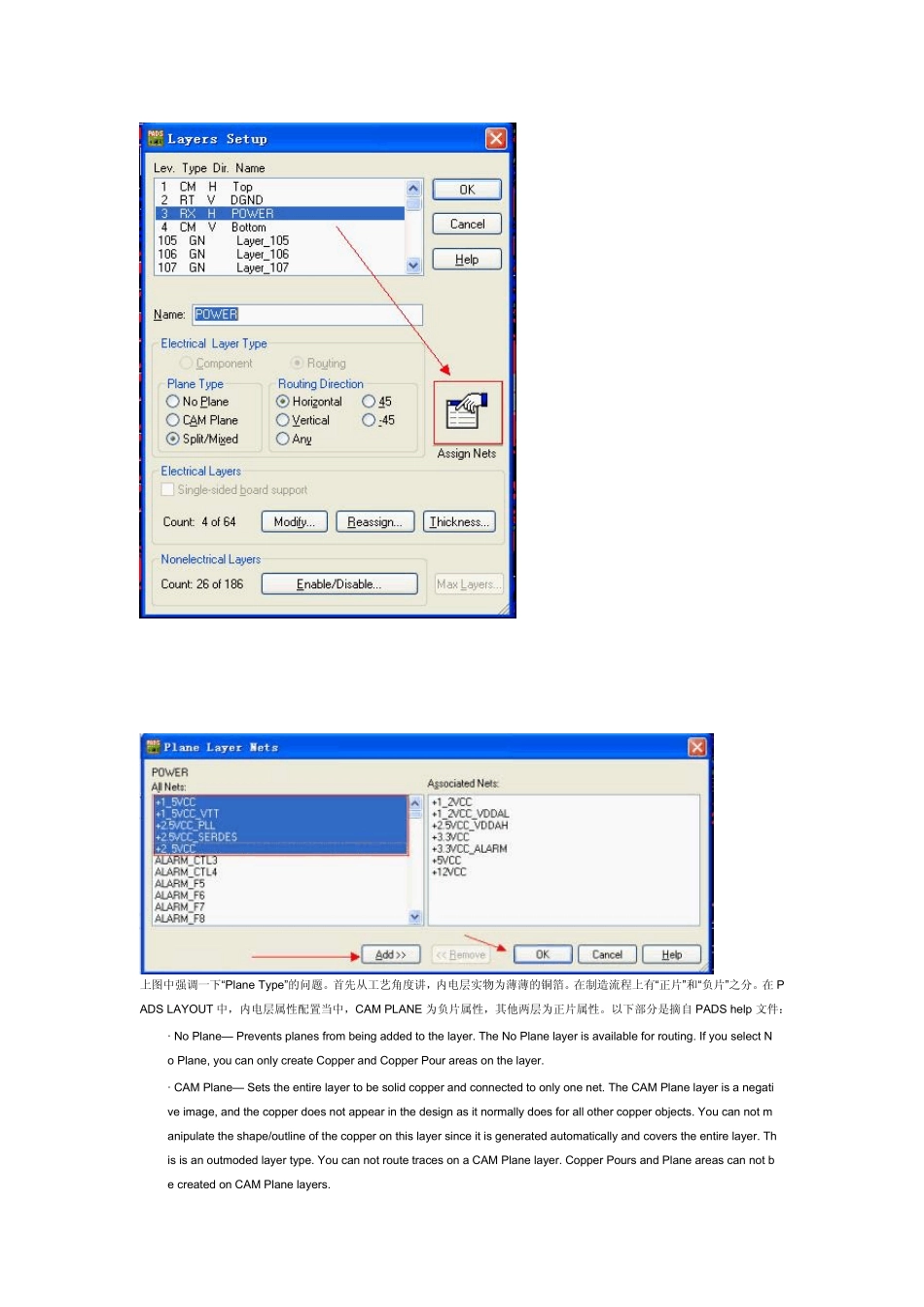
四层板堆叠一般为:SIG1/GND/POWER/SIG2; 六层板堆叠为:① SIG1/GND/SIG2/SIG3/POWER/SIG4; ② SIG1/GND1/POWER/SIG2/GND2/SIG3; 在 PADS 当中板层定义如下图所示: 其次,为电源层分配电源网络
上图中强调一下“Plane Type”的问题
首先从工艺角度讲,内电层实物为薄薄的铜箔
在制造流程上有“正片”和“负片”之分
在 PADS LAYOUT 中,内电层属性配置当中,CAM PLANE 为负片属性,其他两层为正片属性
以下部分是摘自 PADS help 文件: · No Plane— Prevents planes from being added to the layer
The No Plane layer is available for routing
If you select No Plane, you can only create Copper and Copper Pour areas on the layer
· CAM Plane— Sets the entire layer to be solid copper and connected to only one net
The CAM Plane layer is a negative image, and the copper does not appear in the design as it normally does for all other copper objects
You can not m